While working with families in the Family Editor or working in the Project Manager, you can create a 3D solid by extruding a 2D profile.
 Video: Create an Extrusion
For information about using extrusions in families, see Constraining Family Geometry.
A solid or void extrusion is the easiest form to create. You sketch a 2D profile of the form on a work plane, and then extrude that profile perpendicular to the plane on which you sketched it.
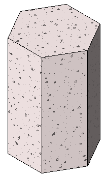
Sample polygonal concrete isolated foundation extrusion
Before you extrude the shape, you can specify its start and end points to increase or decrease the depth of the form. By default, the extrusion start point is 0. The work plane does not need to be either the start or end point of the extrusion – you only use it to sketch on and to set the extrusion direction.
The following procedure is a general method for creating a solid or void extrusion. Steps may vary depending on your design intent.
To create a solid or void extrusion
- In the Family Editor, on the Create tab
 Forms panel, do one of the following:
- Click
 (Extrusion).
- Click Void Forms drop-down
 (Void Extrusion).
Note: If necessary, set the work plane before you sketch the extrusion. Click Create tabWork Plane panel (Set).
- Click
- Use the sketching tools to sketch the extrusion profile:
- To create a single solid form, sketch a closed loop.
- To create more than one form, sketch multiple, non-intersecting, closed loops.
- On the Properties palette, specify the extrusion properties:
- To extrude the profile from the default start point of 0, under Constraints, for Extrusion End, enter a positive or negative extrusion depth.
This value changes the endpoint of the extrusion.
Note: The extrusion depth is not retained after you create the extrusion. If you need to make multiple extrusions with the same endpoint, sketch the extrusions, select them, and then apply the endpoint. - To extrude the extrusion from a different start point, under Constraints, for Extrusion Start, enter a new point.
- To set the visibility of a solid extrusion, under Graphics, for Visibility/Graphics Overrides, click Edit, and specify the visibility settings.
- To apply a material to a solid extrusion by category, under Materials and Finishes, click in the Material field, click
 , and specify a material.
- To assign a solid extrusion to a subcategory, under Identity Data, for Subcategory, select a subcategory.
- Click Apply.
- To extrude the profile from the default start point of 0, under Constraints, for Extrusion End, enter a positive or negative extrusion depth.
- Click Modify | Create Extrusion tabMode panel
 (Finish Edit Mode).
Revit completes the extrusion and returns you to the view in which you started the extrusion.
- To view the extrusion, open a 3D view.
- To resize the extrusion in the 3D view, select it and use grips to edit it.