When working with families in the Family Editor, you can create a solid 3D shape that changes along its length, blending from a starting shape to an ending shape.
 Video: Create a Blend
For information about using blends in families, see Creating Family Geometry.
The Blend tool blends 2 profiles (boundaries) together. For example, if you sketch a large rectangle and a smaller rectangle on top of it, Revit blends the 2 shapes together.
Video: Create a Blend
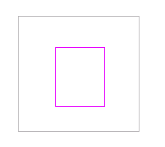
Sample base and top boundaries for a blend.
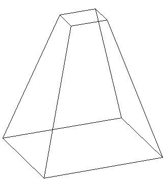
Finished blend
To create a solid or void blend
- In the Family Editor, on the Create tab
 Forms panel, do one of the following:
- Click
 (Blend).
- Click Void Forms drop-down
 (Void Blend).
Note: If necessary, set the work plane before you sketch the blend. Click Create tabWork Plane panel (Set).
- Click
- On the Modify | Create Blend Base Boundary tab, use the Draw tools to sketch the base boundary of the blend, for example sketch a square.
- To specify the depth of the blend, on the
Properties palette, do either of the following:
- To specify a depth that is calculated from a default start point of 0, under Constraints, for Second End, enter a value.
- To specify a depth that is calculated from a start point other than 0, under Constraints, enter Second End and First End values.
Note: If specified, Revit does not retain the end point value during creation of the blend. If you need to make multiple blends with the same end point, first sketch the blends, then select them, and then apply the end point.
- When finished with the base boundary, on the Modify | Create Blend Base Boundary tabMode panel, click
 (Edit Top).
- On the Modify | Create Blend Top Boundary tab, sketch a boundary for the top of the blend, for example another square.
- If necessary, edit the vertex connections to control the amount of twist in the blend:
- On the Modify | Create Blend Top Boundary tab, click Mode panel
 (Edit Vertices).
-
Vertex points become available on one of the blend sketches.
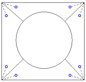
The dotted lines with blue open-dot controls are suggested connections. Each control is a switch between adding and removing connections.
- To display the vertex points on the other blend sketch, on the Edit Vertices tabVertex Connect panel, click
 (Controls on Base) or
 (Controls on Top) - whichever option is currently unselected.
- Click a control, and the line becomes a solid connection. A filled blue control displays on the connection.
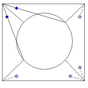
- Click a solid control to remove a connection; the line reverts to a dashed line with an open dot control.
-
As you click the controls, some possible edges disappear and other ones appear.
- On the Vertex Connect panel, click
 (Twist Right) or
 (Twist Left) to twist the selected blend boundary in a clockwise or counter-clockwise direction.
- On the Modify | Create Blend Top Boundary tab, click Mode panel
- On the
Properties palette, specify the blend properties:
- To set the visibility of a solid blend, under Graphics, for Visibility/Graphics Overrides, click Edit, and specify the visibility settings.
- To apply a material to a solid blend by category, under Materials and Finishes, click in the Material field, click
 , and specify a material.
- To assign a solid blend to a subcategory, under Identity Data, for Subcategory, select a subcategory.
- Click Apply.
- Click Modify | Create Blend Top BoundaryMode panel
 (Finish Edit Mode).
- To view the blend, open a 3D view.
- To resize the blend in the 3D view, select and use grips to edit it.