In a family, place a connector on a face or on a work plane.
Place a Connector on a Face
- In the Family Editor, in the Project Browser, double-click Views (all)
 3D Views3D, and spin the model to view the face where you want to place a connector.
The first connector that you place for a specific type is assigned as the primary connector. You can change the assignment later.
- Click Create tabConnectors panel, and click a connector type, such as Duct Connector.
- Place the cursor over the face that is on the X axis. After the edges highlight, click to place the primary connector. (By default, is already selected.)
The primary connector is placed.
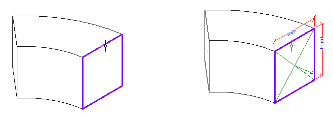
- Select the connector and specify instance properties as needed.
The sizes and orientation that you specify determines how connections are made with compatible components. You can enter parameter values or associate them with family parameters for the component.
Place a Connector on a Work Plane
- In the Family Editor, open a plan view and a 3D view where you want to place a connector.
The first connector that you place for a specific type is assigned as the primary connector. You can change the assignment later.
- Click Create tabConnectors panel, and click a connector type (Electrical, Duct, Pipe, Cable Tray, or Conduit).
For example, click Electrical Connector, and click Modify | Place Electrical Connector tab
Placement panel (Work Plane).
- In the Work Plane dialog, select the work plane where you want to place the connector, and click OK.
In this example, an electrical connector is placed on the top work plane of a junction box.
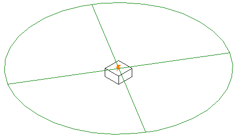
- Select the connector, move it, and specify instance properties as needed.
You can enter parameter values or associate them with family parameters for the component.