Connectors can be linked together to designate flow through the family.
Linked connectors only have an effect when the System Type is set to Global, which is common for fittings and in‐line components such as dampers, valves, and pumps. Essentially, Revit will try to discern the system type, flow direction, and flow values if the connectors are linked.
Use this command when you want system behavior to pass from one connector to another. Linking connectors also makes it possible to use equipment as inline components in a system. For example, since pipe fittings do not have parameters for storing the fluid or air flow, when you link the connectors for a pipe fitting, Revit propagates system information through the fitting.
- In the Family Editor, open a view containing the connectors being linked.
- Select a connector.
- Click Modify | Connector Element tab
 Connector Links panel
 (Link Connectors). Then select the connector that will be linked to the first connectors).
 - Select either of the linked connectors.
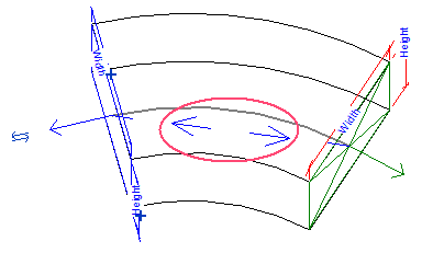
Arrows display between the connectors to indicate the link.