When you start a piping plan, you need to specify the routing preferences for the type of pipe being placed in the plan. If the routing preferences for the selected pipe type have not already been specified, go to Specifying Routing Preferences for Pipe.
- In the Project Browser, expand Views (all)
 Floor Plans and double-click a view for the piping system.
 - Click Systems tabPlumbing & Piping panel
 Flex Pipe.
 - In the Type Selector, select a flex pipe type.
- On the Options Bar, specify layout options.
- On the Place Pipe tabPlacement Tools panel, select placement options.
- On the ribbon, verify that
 Tag on Placement is selected to automatically tag pipes. Then specify the following tagging options on the Options Bar:
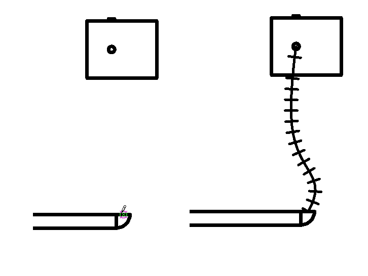
If you want to ... then ... change the orientation of the tag select Horizontal or Vertical. load additional tags click Tags. include a leader line between the tag and the pipe select Leader. change the default length of the leader enter a value in the text box to the right of the Leader check box. - In the drawing area, click to specify the start of the flex pipe, drag to extend the flex pipe preview along the path that you want the flex pipe to follow. Click at each point where the flex pipe should bend and finally, click a connector to end the flex pipe at its destination (another pipe segment, mechanical equipment component, or pipe fitting).
Some components have multiple connectors that display stacked one above another. When drawing flexible pipe from a stacked connector, a Select Connector dialog displays to let you specify which connector to use.
Transitions and tees are automatically added to the segment.
Flex pipes display with centerlines in hidden line view. For pipe fittings, you can override the default centerline by editing the family, adding a model line, and setting its subcategory to centerline.
By default, centerlines are turned off in U.S. templates.