Use Slope tools to define parameters for sloped MEP fabrication pipework.
Slope tools for MEP fabrication pipework are similar to slope tools for generic pipework parts. Many commands and workflows behave the same for both generic and fabrication sloped pipe. For more information on generic sloped pipe features, see Draw Sloped Pipe and Use the Slope Editor.
Slope tools for MEP fabrication pipework display and can be specified in the contextual ribbon when you:
- place pipe parts using part-by-part placement from the MEP Fabrication Parts palette
- place pipe parts with the multi point routing tool
- select a fabrication pipe part in a model
To specify slope as you begin creating a new MEP fabrication pipe run:
- In the MEP Fabrication Parts palette, select the part to insert.
- Click Modify | MEP Fabrication Pipework tab
 Options panel, and specify any of the following pipe slope controls before placing the first part:
- Slope: Set the slope to Up, Down, or Off.
- Slope Value: When Slope is set to On, specifies the slope value for drawing sloped pipe in a fabrication run. The values displayed in this dropdown are defined in Mechanical Settings. For more information, see Mechanical Settings for Piping.
- Justification: Aligns the sides of an eccentric transition when placed in a fabrication model. Options are Middle, Top, or Bottom.
To add or edit the slope of a fabrication pipe part that has already been inserted into a model:
- In the model, select the pipe part.
-
Click Modify | MEP Fabrication Pipework tab
Modify panel Slope.
The Slope Editor displays.
-
Use the Slope Editor tools to specify values.
For more information, see Draw Sloped Pipe and Use the Slope Editor.
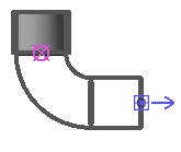
By default, fabrication pipe parts that are sloping down display a blue arrow on open connectors, as shown below.
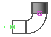
Fabrication pipe parts that slope up display a green arrow by default, as shown below.