- Open the view where you want to place the cable tray.
- Click Systems tab
 Electrical panel
 Cable Tray.
 - From the Type Selector, select the cable tray type, with or without fittings.
- On the Options Bar, specify the width, height, offset, or bend radius.
- On the ribbon, verify that Tag on Placement is selected to tag the cable tray automatically. Then specify the following tagging options on the Options Bar:
If you want to... then... change the orientation of the tag select Horizontal or Vertical. load additional tags click Tags. include a leader line between the tag and the cable tray select Leader. change the default length of the leader enter a value in the text box to the right of the Leader check box. - On the ribbon, select placement options.
- In the drawing area, click to specify the start of the cable tray run, then move the cursor and click to specify points along the run.
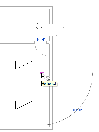
A bend is automatically added to the segment as needed.
Note: When you draw cable tray with fittings, connection lines for the fittings are displayed.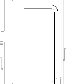
- To draw vertical cable tray, on the Options Bar, specify the offset value, and continue drawing the run. Note: When drawing cable tray without fittings, if you draw cable tray across existing cable tray at the same elevation, then either the new cable tray will be broken (if they are the same size), or the smaller of the two cable tray runs will be broken.
- To finish the cable tray run, click Modify.