Hydraulic separation provides flow and pressure loss calculations for piping loops.
When you separate hydronic piping systems into primary, secondary, and tertiary loops, calculated flow and pressure loss calculations for each additional loop display on the pump for that loop. The aggregate of the flow values displays on the pump or pump set in the primary loop. The pressure drop reported for a pump reflects the portion of the piping network the pump feeds. As a result, the pump on a primary loop reports the pressure drop for the primary loop. The pump on a secondary loop reports the pressure drop for the secondary loop, and so on.
- A single source equipment component, such as a boiler or chiller. This component is optional.
- A single pump or pump set per loop (primary, secondary, tertiary, and further) if you want to calculate flow and pressure drop for each loop.
- Any number of loads, such as radiators or fan coil units on the secondary and/or additional loops. Radiators and other terminals can be piped in series.
- Any number of pipe segments in the supply sections and return sections of the network.
- The primary loop configured in a loop or using a header.
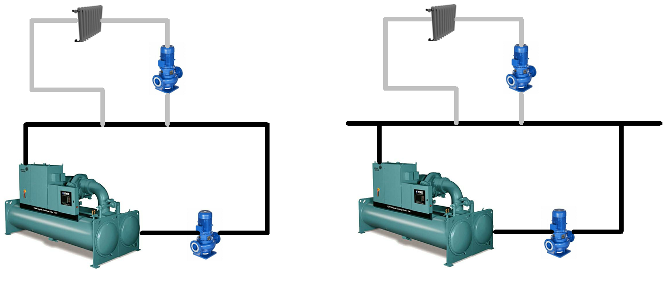
Hydronic networks before separation - primary loop (left) and primary loop with low loss header (right)
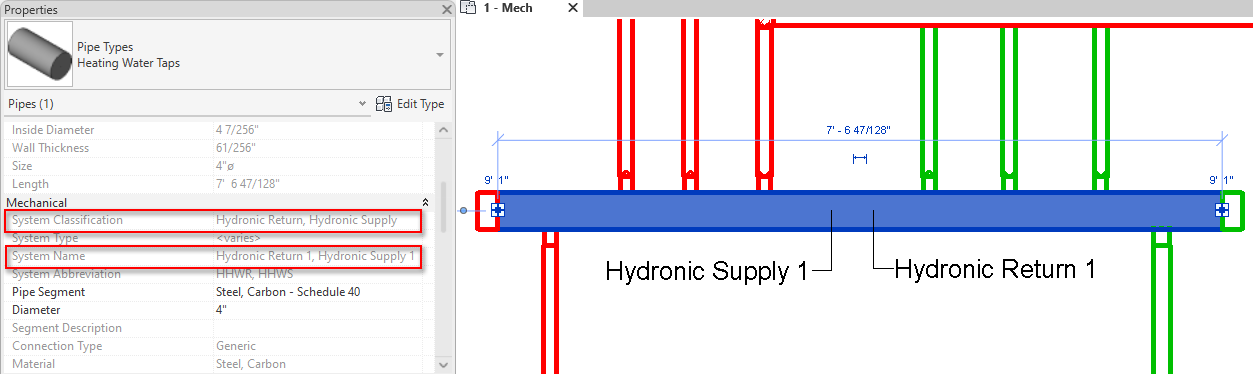
Loops are separated analytically: the secondary loop from the primary, the tertiary from the secondary, and so on, as needed. Each loop is assigned to its own system for supply and return. As a result, the primary and secondary systems use the same system type, but are assigned different system instances. The System Name of the secondary systems is appended with a period followed by a number. For example, a network consisting of one primary loop and two secondary loops uses a supply system named Hydronic Supply 1. After hydraulic separation, the network consists of a primary loop that named Hydronic Supply 1 and two secondary loops named Hydronic Supply 1.1 and Hydronic Supply 1.2.
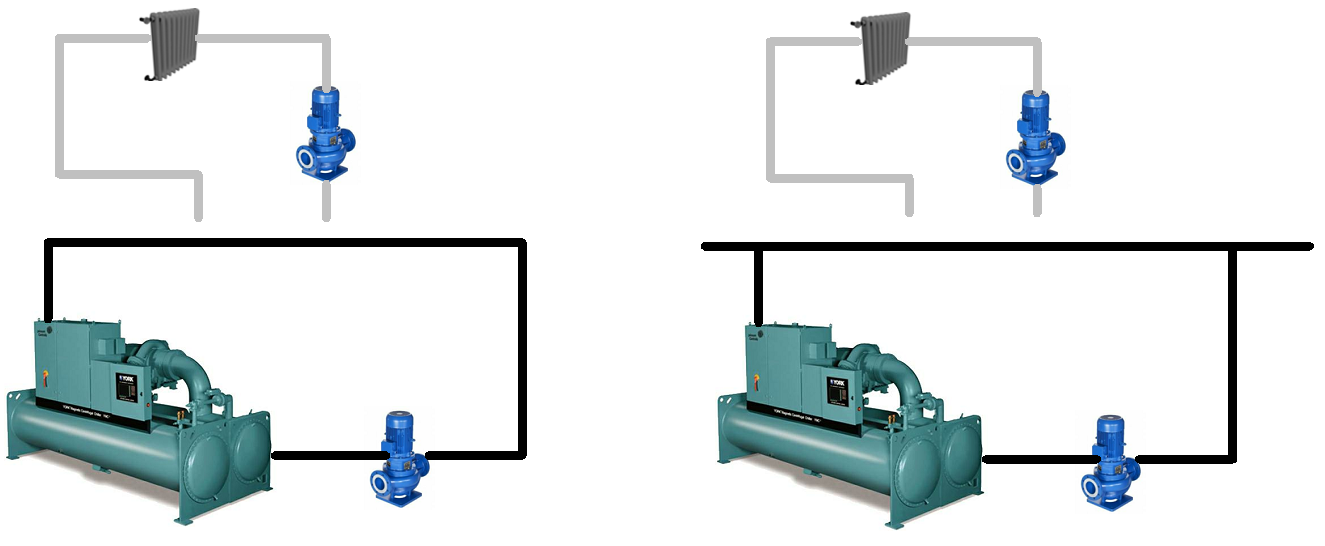
Hydronic networks after separation - primary loop (left) and primary loop with low loss header (right)
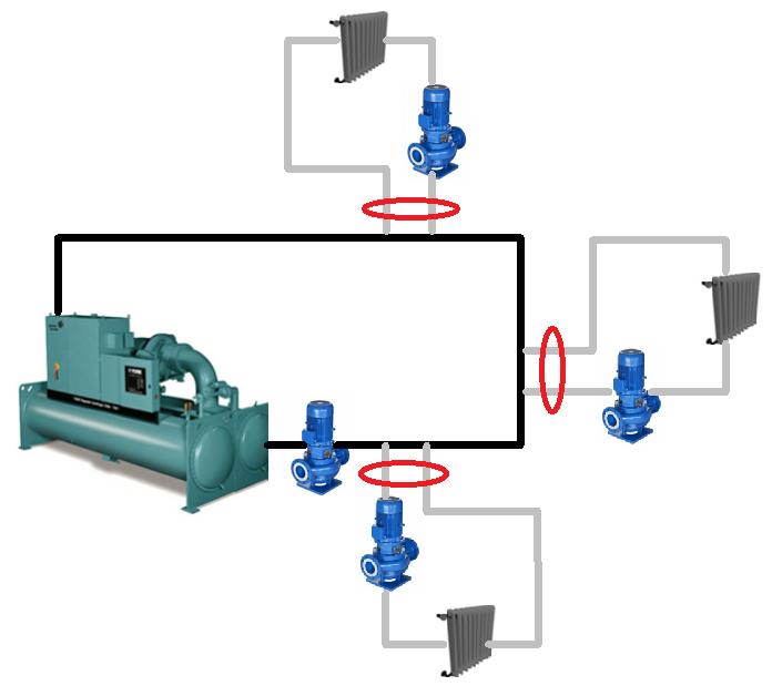
- Parallel zones are piped so that the primary loop is divided into several crossover branches which serve the secondary zones through closely spaced tees. In this case, there is a common pipe for each secondary loop.
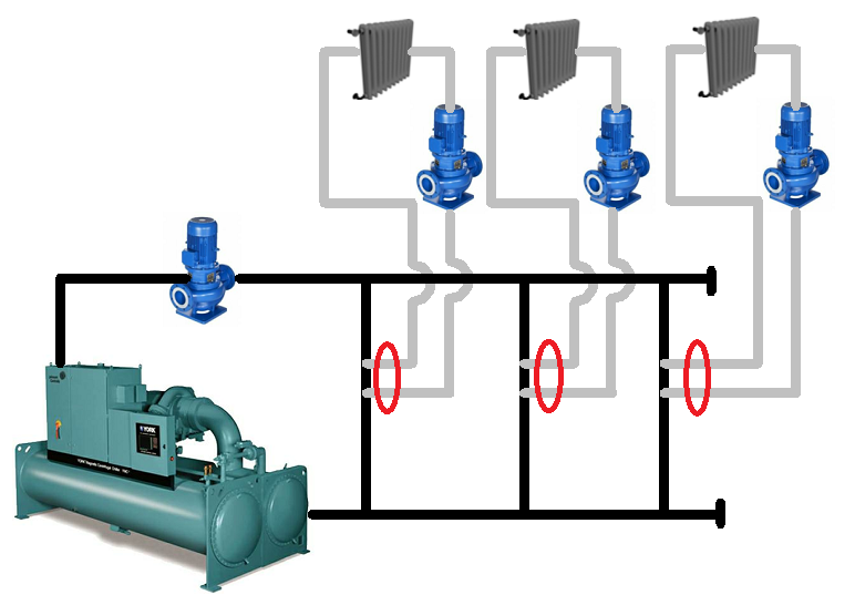
Primary loop with crossover bridges - red indicates which pipes are selected for separation
- The flow in a one-pipe primary is equal to the highest flow of the connected secondary loops. The flow in the common pipe associated with the secondary loop with the highest flow displays zero for flow and the common pipes of the other secondary loops will display a flow that is the difference between the primary and that secondary.
Primary loop with secondary loops with direct and/or reverse return networks - red indicates which pipes are selected for separation
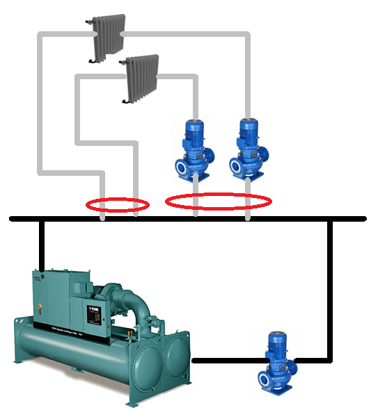
Primary loop with a low loss header - red indicates which pipes are selected for separation