View and modify the instance properties for piping.
| Parameter | Description |
|---|---|
| Mechanical | |
| System Classification |
Defines the system for the connectors that are located on equipment. For example, piping equipment could have a system classification of Hydronic Supply, Hydronic Return, Sanitary, Vent, Domestic Hot Water, Domestic Cold Water, and so on. These values are pre-defined classifications within Revit. |
| System Type |
Defines the system types for an MEP system. You can duplicate an existing system type to create additional system types as needed for the model. For example, if you need a system type for high pressure supply air, duplicate the Supply Air system type, rename it, and change the properties as needed. |
| System Name | A name that uniquely identifies a system, it may be user-defined or automatically generated. |
| System Abbreviation | A user-defined abbreviation for a system. |
| Loss Method | Defines the loss method for the selected fitting. |
| Loss Method Settings | Defines the loss method settings used when calculating pressure drop for a pipe fitting. |
| Pipe Segment | Defines the content used for a pipe section. |
| Diameter | Defines the nominal diameter for a pipe section. |
| Segment Description | A user-defined description for a pipe segment. |
| Connection Type | Defines the type of connection for a pipe fitting or section, such as welded, threaded, grooved, glued, soldered, or flanged. |
| Material | Defines the material for a pipe section. |
| Schedule/Type | Displays the schedule or type for the selected pipe. |
| Roughness | Defines the roughness for a pipe section. |
| Area | Defines the surface area of pipes, ducts, conduits, and cable trays. |
| Mechanical - Flow | |
| Critical Path | Indicates whether the selected pipe is on the critical path of the network. Revit calculates the pressure drop of each path and specifies the one with the largest pressure drop as the critical path. You can set up a view filter or system color fill scheme to display the critical path. See About Controlling Visibility and Graphic Display of Elements Using Filters. |
| Section | Defines a run of segments and fittings that have the same velocity, for example, the same flow, size, and shape. |
| Additional Flow | Defines the additional flow for the selected pipe. |
| Flow | Displays the flow rate for the pipe or pipe connector. |
| Relative Roughness | This value is calculated using the following formula:
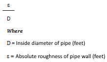 |
| Reynolds Number | This value is calculated using the following formula:
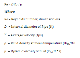 |
| Flow State | The flow state is determined by the value of the Reynolds Number. A Reynolds Number less than 2,000 is considered laminar flow. A Reynolds Number greater than 4000 is considered turbulent flow. Numbers between 2,000 and 4,000 are unpredictable and no loss calculation is made. There are two types of turbulent flow: transition and complete turbulence. |
| Velocity | This value is calculated using the following formula:
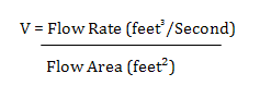 |
| Velocity Pressure |
Displays the difference between the total pressure and static pressure for the selected duct. |
| Friction Factor | Friction factor used in Darcy-Weisbach equation is calculated based on the flow state
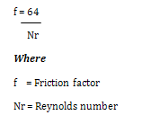 Laminar Flow 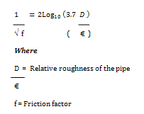 Turbulent Flow |
| Friction | The pressure loss for a specific length unit of pipe. |
| Pressure Drop | Displays the pressure drop for the selected pipe, fitting, or connector. To see the pressure drop for each path through the fitting, check the pressure loss report. |