This method places a space in complex areas where the volume of the complex area is constrained from a base level to a level above.
You can use this method when placing spaces for areas such as those that span multiple levels, those having a cantilevered upper level, or areas having a loft as the upper limit for a portion of the area. For these situations, space separation lines or additional levels can be used to divide these areas.
In the Project Browser, double-click the floor plan containing the base level for the area that spans multiple levels.
Next, you create a section view to verify the spaces vertically as you place them.
Create section views
- Click View tab
 Create panel
 (Section).
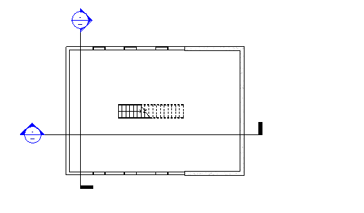
- In the floor plan view, draw 2 perpendicular sections across the floor plan as shown.
Make certain that the section line intersects the area that you are placing the space. If not, the space will not display in the section view.
- In the Project Browser, double-click the new section view to open it.
You can use an existing section view but make certain that the section line intersects the area where the spaces will be placed.
Create levels
- Click Modify.
This topic assumes that standard levels exist in the design and that they do not need to be created. If levels do not exist, then you need to create them.
Divide the area using space separation lines
- Click in the floor plan to make it the active view.
- Click Analyze tabSpaces and Zones panel
 (Space Separator), and draw a space separator to divide the area according to the different upper limits.
Note: Space separation lines are room-bounding components.
(Space Separator), and draw a space separator to divide the area according to the different upper limits.
Note: Space separation lines are room-bounding components.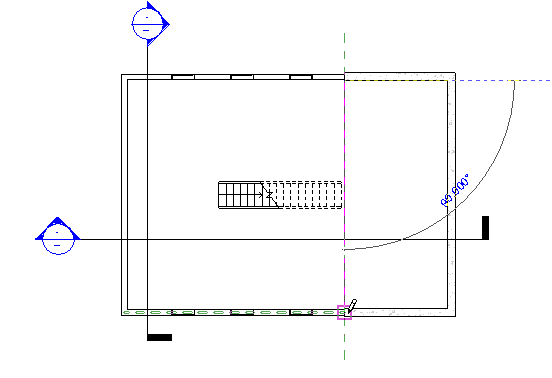
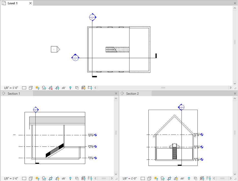
- In the Project Browser, open both new section views.
- Close all views, except the 2 section views and the floor plan where you want to place the space, and type
w t on the keyboard to tile the 3 views.
You can also click View tab
Windows panel (Tile Views).
Activate spaces visibility
- Click in a section view to make it active.
- Type v g on the keyboard.
- On the Model Categories tab of the Visibility Graphics dialog, scroll down to Spaces.
- Expand Spaces, select Interior and Reference (if you want to display reference crosshairs), and click OK.
- Repeat to make spaces visible in the other section view and the floor plan view.
Place a space
- With the floor plan view active, click Analyze tabSpaces and Zones panel
 (Space).
Note: You may need to load space tags in the project, if they are not already loaded.
(Space).
Note: You may need to load space tags in the project, if they are not already loaded. - On the Options Bar, do the following:
- For Upper Limit, specify the level above.
When specifying the upper limit for a space beneath a roof, specify the upper limit to the level that is located above the top of the roof so that the space will snap to the roof. If such a level does not exist, create it. See Placing Spaces Up to the Roof for more information.
- For Offset, enter
0' 0" (0.00 mm).
These 2 options specify the vertical extent or height of the space.
Note: If the upper limit and offset are specified beyond the level above, the vertical boundary of the space will snap to a room-bounding component, such as a ceiling or a floor, even though the upper limit is higher than the room bounding component. This is because with the Areas and Volumes option selected (default setting), the vertical boundary of the space will snap to room-bounding components, such as ceilings, floors, or roofs. The volume of the space will be calculated up to the room-bounding component. The Areas and Volumes option is located on the Architect tabRoom & Area panel drop-downArea and Volume Computations.
- In the Space box, either verify that New is selected if placing a new space, or select an unplaced space from the list to place it.
- Tag on placement: Places a space tag upon placement of the space.
Tag on placement is selected by default. If Tag on placement is selected, you can select the tag type from the Type Selector.
- Tag location box: specifies either Horizontal, Vertical, or Model as the space tag location.
Applicable only if Tag on placement is selected.
- Leader: Creates a leader line for the space tag.
Applicable only if Tag on placement is selected.
- Show Bounding Elements: Highlights the room-bounding elements in the building model for immediate recognition.
Select the following options as needed:
- For Upper Limit, specify the level above.
- In the floor plan view, move the cursor over an area in the building model, and click to place a space.
Note: Spaces can only be placed in floor plan views.
- Click Modify.
- Select the space.
- On the Properties palette, under Energy Analysis, do one of the following:
- Select Occupiable, if the space will be occupied.
- Clear Occupiable, if the space will be unoccupied.
- Click OK.
Note: If you place a space in an area that contains a room, the Occupiable parameter is automatically selected. This defines the space as occupied. If the area does not contain a room, the Occupiable parameter is automatically cleared. This defines the space as unoccupied. You can always redefine the space by selecting or clearing this parameter. The Occupiable parameter affects the System Analysis.
Verify the spaces
- In the section and floor plan views, verify that the shaded areas representing the volume of the spaces are constrained from the base level to the level above, and that unshaded areas (caused by such things as cavities or shafts) do not exist. This provides for a more accurate volume calculation.
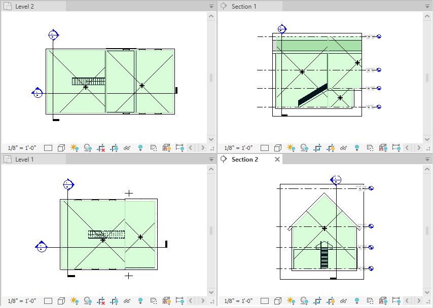
- If the space is not constrained as specified, in the section view, verify that the upper limit of the space is specified to the level above, and
redefine the space vertically, if necessary.
You must also resolve all unshaded areas.
Other complex spaces can be divided using space separation lines or levels as shown.
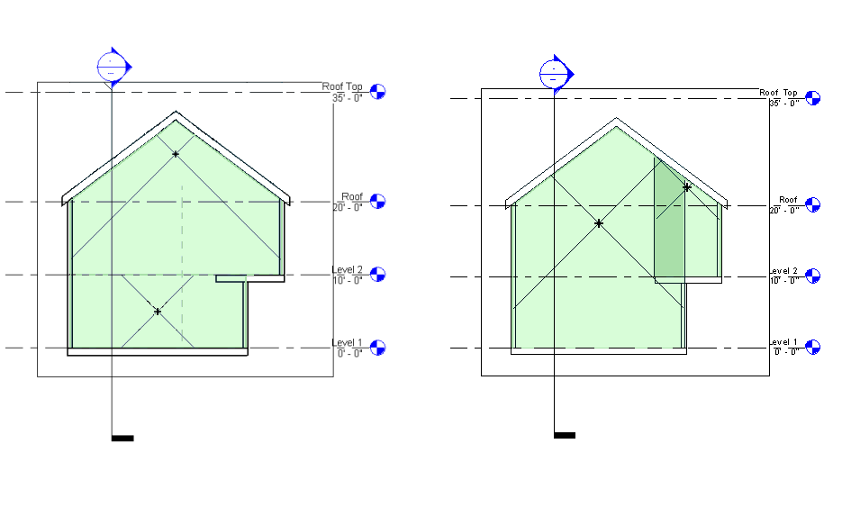
Left example: A level divides the area horizontally. The lower area has its base as Level 1 and its upper limit as Level 2. A second space is specified with its base as Level 2 and its upper limit as the Roof Top level.
Right example: A space separation line divides the area vertically. The lower area has its base as Level 1 and its upper limit as at the Roof Top level. Space 2 uses Level 2 as its base and the Roof Top level as its upper limit.