You can use the Add Split Line tool to add linear edges and to split the existing face of an element into smaller sub-regions.
- Select the element to modify.
- Click Modify | <element> tab
 Shape Editing panelAdd Split Line.
- Select a vertex, edge, face or point anywhere on the surface to start the split line. Use the controls on the Ribbon to set the position of the split line.
- Along Surface
 - Split line is added in relation to the surface. Value displayed near the cursor reports the elevation of the surface based on the Elevation Base setting. The line will be added using the Offset from Surface value.
- Absolute
 - Split line is added based on the Elevation Value. Value displayed near the cursor reports the elevation of the surface based on the Elevation Base setting.
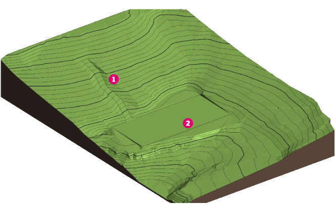
For example when working with a toposolid, place split lines along the surface to create a path way , or place split lines at an absolute elevation to create a flat area
 .
.
 Note: If your cursor is over a vertex or edge, the editor will snap to 3D vertices and edges and present standard snap controls with temporary dimensions along the edges. If no vertex or edge is snapped to, then on selection, the line end will be positioned in relation to the surface based on the settings in the Ribbon. No temporary dimensions will be created on the face.
 - Along Surface
- Select another vertex, edge, face or point anywhere on the element to end the split line.
A new edge will be added to the face.
 Note: Fold lines in elements can be converted to split lines when shape editing. See Convert Folding Lines to Split Lines for additional information.