The algorithm for deflections of RC slabs is based on the use of calculations of an isotropic elastic slab made of an elastic material. Changes of material stiffness due to cracking are considered. Displacements are calculated applying the Finite Element Method (FEM), then they are modified.
Calculations are performed separately for each panel. Such an assumption is correct if a panel can be identified with a structural element (span, floor segment), otherwise stiffness values averaged within a panel may be distorted. This may result in the influence of very distant elements on displacements of an analyzed FE. Influence of such disturbances on extreme values is not very significant, however deformation (deflection) maps should be treated with great caution.
It is recommended to model each floor segment where local extremes of deflections may occur as a separate panel. That panel should be defined within the limits set by the supports around it (similarly as spans which are limited by supports in the case of beams). For a panel, these supports do not need to be continuous throughout the whole panel contour.
Division to panels does not affect the results of verification using the With stiffness update (FEM) method provided that loads, geometry and calculated reinforcement are the same.
Calculations are performed for a selected combination (separate for the lower and upper displacements) or a combination group, if that is required by the code (frequent, rare and quasi-permanent combinations). That combination is chosen for calculations for which there are maximum elastic displacements (positive and negative separately). If a panel may not be treated as a structural element (it comprises more structure elements), deformation (deflection) maps should be treated with great caution. It has, however, no significant influence on extreme deflection values for a given panel.
One should pay attention to displacements of the remaining supported corners of a slab.
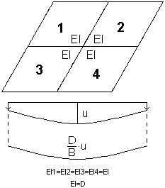
The calculation algorithm used in the Robot program is based on the assumption that the total (real) deflections of an RC slab equal the product of its elastic deflections and the stiffness coefficient D / B.
where:
![]() - Real displacements of i-th calculation point of a slab which take account of cracking and calculated reinforcement
- Real displacements of i-th calculation point of a slab which take account of cracking and calculated reinforcement
![]() - Elastic displacements of i-th calculation point of a slab
- Elastic displacements of i-th calculation point of a slab
D - Slab stiffness assuming elasticity of the material (as in FEM calculations)
B - Equivalent stiffness of an RC slab, calculated considering element cracking, rheological effects, adherence of calculated reinforcement, etc. and averaged for both directions.
Such an approach comes down to linear scaling of individual elastic displacements by the global coefficient of stiffness reduction.
Limitation of FEM stiffness update method
Due to the mutual interaction between panels, warning "Stiffness update during deflection verification process is limited to the selection of panels taken into account during analysis process." has been added. It appears always when any of the panels is not taken into account in the calculations.
The program performs calculations regardless of the number of panels considered in the verification. However, it is important to pay attention to the fact that if not all panels that significantly influence each other are taken into account in the analysis, the analysis results may be incorrect. The value of error depends on the magnitude of the interaction (change of the stiffness) between the analyzed panels and those that are not considered in the deflection verification with stiffness update method (FEM).
The calculation algorithm for the equivalent stiffness (elastic) method is as follows:
After performing the structure analysis using FEM and calculating the required reinforcement area for the ultimate limit state, the serviceability limit state (as regards cracking calculations, stress limits, or other issues that may be considered locally) and the accidental limit state, stiffness for each finite element (FE) is evaluated in the program. Stiffness calculations are carried out for two directions of reinforcement. The scope and method of calculating these stiffness values depends on detailed requirements of a given code. As a result of these calculations, two stiffness values (different in most cases) are obtained for each finite element. For further calculations, a weighted average of component stiffness values is used. The weight for averaging is the ratio of moments acting on a given element in both directions.
where:
Bx, By - Real stiffness values calculated for two directions of reinforcement
cf - Weight coefficient calculated according to the formula.
- If | Mxx | / | Myy | > 4, then cf = 1
- If 0.25 ≤ | Mxx | / | Myy | ≤ 4, then

- If | Mxx | / | Myy | < 0.25, then cf = 0.
As a result of applying these formulas, in the case of large disproportion of moments (the ratio of the larger to the smaller moment is greater or equal to 4.0), the stiffness from the direction of action of the larger of the moments is taken into account. When values of moments are similar, the thickness from a given direction is ascribed in proportion to the moment ratio.
The next step is to evaluate the ratio of the elastic stiffness to the weighted average of real stiffness values obtained as mentioned above. Such calculation is performed for each finite element.

The slab coefficient (1 - n*n) is considered in calculations of the stiffnesses B and D.
Real stiffness values obtained in calculations may be viewed by switching on maps of Stiffness factor.
If properties of materials used during design are identical to those used in a model, then the value of the coefficient D / B > 1.0. This coefficient can be interpreted (mainly for slabs subjected to unidirectional bending) as an elastic deflection multiplier. If different materials are used in a model and calculations (for example, with different classes such as concretes with different Young's modulus or Poisson's ratio), the coefficient value is corrected automatically. It may result in disturbing the earlier mentioned inequality.
The subsequent step is to calculate the average of the stiffness ratios evaluated earlier. The final global stiffness ratio, used for calculation of real displacements of a slab (such as linear scaling of elastic displacements) is an average of the average of stiffness ratios (with the weight equal to 0.25) and the stiffness ratio recorded for an element in which there is the extremum of the bending moment acting in any direction (with the weight equal to 0.75).
The equivalent stiffness (elastic) method algorithm assumes averaging the stiffness for all finite elements; a shape of the deflection line is, therefore, identical to the deflection line multiplied by the stiffness coefficient.

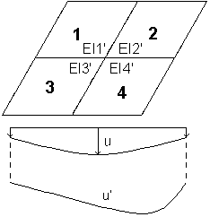
The algorithm of the method with stiffness update (inelastic) is identical to the algorithm of the equivalent stiffness (elastic) method until the calculated stiffness is ascribed independently to each finite element (different stiffness for the X direction and the Y direction). An anisotropic slab of various rigidity is obtained. For thus-determined stiffness values the slab deflection is calculated.
In the method with stiffness update, stiffness of each element is calculated independently, thus deflection lines may differ. A different stiffness is obtained for each finite element for each direction.

If the Reinforcement correction option is selected on the SLS Parameters tab in the Slab and Shell Reinforcement Parameters dialog during calculations, reinforcement area increases (to increase the element stiffness), which reduces slab deflections.
Reinforcement in both directions is distributed in inverse proportion to stiffness. When it is not possible to limit deflections below the user defined admissible deflection value (when further correction of reinforcement due to the allowable reinforcement ratio is impossible), then when calculations of the required reinforcemement area are completed, a warning prompts that the admissible deflection value has been exceeded for the panel.
There are no predefined limits set on reinforcement other than those in codes. Note the economic aspect of the solution provided and that the more a deflection differs from requirements, the less effective the used method is.