This subassembly overlays one side of an existing carriageway, with a levelling layer added as required.
Attachment
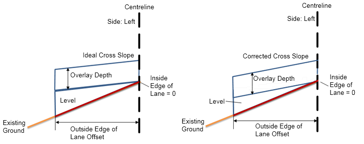
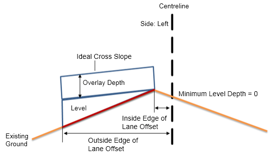
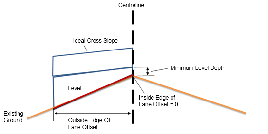
The attachment point is the inside edge point of the overlay layer with finished gradient crossfall.
Input Parameters
| Parameter | Description | Type | Default |
|---|---|---|---|
| Side | Specifies which side of the road centreline to place the subassembly. | Left/Right | Right |
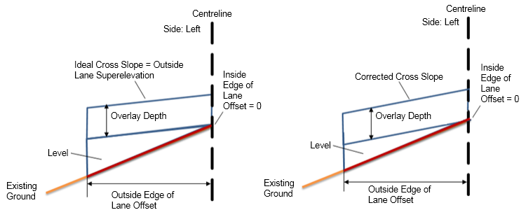
| Overlay Depth | Depth of the overlay layer. | Numeric | 0.300m (0.300 ft) |
| Design Lane Width same as Existing Lane Width |
|
User defined | No |
| Inside Edge of Existing Lane | This is the start point for calculating existing ground slope. | Numeric | 0.000m (0.000 ft) |
| Outside Edge of Existing Lane | This is the end point for calculating existing ground slope. | Numeric | 12.000m (12.000 ft) |
| Overlay Slope Options | Specifies overlay slope options.
Tip: Flapping is a term used to describe how the corrected cross slope for an overlay in a rehab subassembly is calculated. Flapping outcomes are different, relative to the slope tolerance and the slope difference between existing ground cross slope and ideal cross slope. If the slope difference is less than the slope tolerance for the subassembly, then the use case is considered "within tolerance". If the slope difference is greater than the slope tolerance for the subassembly, then the use case is considered "outside of tolerance".
Note: Slope tolerance is an absolute value. Therefore, for either a slope difference of 0.4% or -0.4%, both have an absolute value of 0.4%. If the slope tolerance is 0.5%, the 0.4% absolute slope difference would be considered within tolerance.
|
User Defined | Match slope |
| Ideal Crossfall | Specifies user-defined ideal crossfall. | Numeric | -2.00% |
| Lane Width | The lane width, determined by the offset of the outside edge of lane from the inside edge of lane. | Numeric | 0.000m (0.000 ft) |
| Use Profile Options | Select to tie the inside edge of the overlay layer to a profile, adjust elevation to minimum level depth or lock to previous subassembly.
|
User defined | Minimum Level Depth |
| Minimum Level Depth | The minimum level depth between the existing surface and the bottom of the overlay layer. | Numeric | 0.300m (0.300 ft) |
| Slope Tolerance | The amount that the overlay crossfall is allowed to vary from the existing ground crossfall or the ideal crossfall. | Numeric, positive | 0.50% |
General Input Parameters
Flapping
Inside Edge of Lane Offset
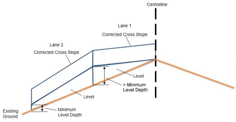
Lock to Preceding 1
In this use case the second lane is set to use the Lock to Previous option. The attachment point for Lane 2 will lock to the elevation of the end of Lane 1. The level depth at the start of the second lane is greater than the minimum level depth specified for that lane.
The corrected cross slope will be calculated and applied, but no elevation adjustment or flapping will be applied. In some cases, the minimum level depth might not be met.
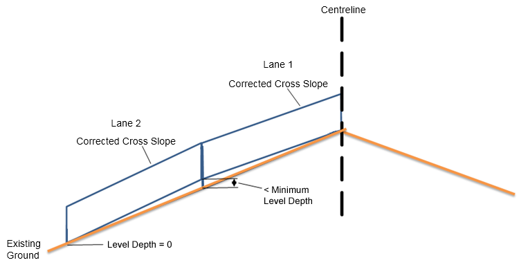
Lock to Preceding 2
In this use case the second lane is set to use the Lock to Previous option. The attachment point for Lane 2 will lock to the subassembly of Lane 1. The level depth at the start of the second lane is less than minimum level depth specified for that lane.
The corrected cross slope will be calculated and applied, but no elevation adjustment or flapping will be applied. In some cases, the minimum level depth might not be met.
Minimum Level Depth
Outside Lane Superelevation
Output Parameters
| Parameter | Description | Type | Default |
|---|---|---|---|
| Corrected Crossfall | This is the adjusted crossfall for the road, which has been optimised to match, as closely as possible, the rehab subassembly parameters you specified. | Numeric | -2.00% |
| Existing Ground Slope | The crossfall (%) of the existing ground profile, calculated from the inside edge of the lane to the outside edge of the lane. | Numeric | percentage |
Target Parameters
| Parameter | Description | Required? |
|---|---|---|
| Target Surface | Name of the surface defining the existing carriageway | Yes |
| Crown Offset Target | Name of the object defining the offset of the crown point. The following object types can be used as targets for specifying this offset: alignments, polylines, feature lines or survey figures. | No |
| Inside Edge of Lane Offset Target | Name of the object defining the offset of the inside edge of lane. The following object types can be used as targets for specifying this offset: alignments, polylines, feature lines or survey figures. | No |
| Lane Width Target | Name of the object defining the offset of the outside edge of lane. The following object types can be used as targets for specifying this offset: alignments, polylines, feature lines or survey figures. | No |
| Inside Edge of Existing Lane Offset Target | Name of the object defining the inside sample point offset will be used to calculate the existing surface slope. The following object types can be used as targets for specifying this offset: alignments, polylines, feature lines or survey figures. | No |
| Outside Edge of Existing Lane Offset Target | Name of the object defining the outside sample point offset will be used to calculate the existing surface slope. The following object types can be used as targets for specifying this offset: alignments, polylines, feature lines or survey figures. | No |
Behaviour
This subassembly assumes that no milling layer is added.
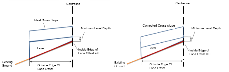
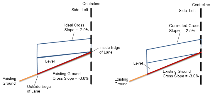
Case 1-1: Ideal Crossfall is greater than Existing Ground Crossfall
| Inputs | |
|---|---|
| Ideal Crossfall | -2.0% |
| Minimum Level Depth | 0 |
| Slope Tolerance | 0.50% |
| Overlay Slope Options | User Defined with Flapping |
| Use Profile Options | Minimum Level Depth |
| Inside Edge of Lane Offset | true (values vary) |
| Outside Edge of Lane Offset | true (values vary) |
| Input | Value |
|---|---|
| Existing Ground Crossfall | -3.0% |
| Existing Ground Crossfall – Ideal Crossfall | -1.0% |
| Slope Tolerance | Existing Ground Slope minus Ideal Crossfall is -1%, which is greater than the 0.5% Slope Tolerance |
| Corrected Crossfall | The Corrected Cross slope will be adjusted to -2.5% |
| Output | Value |
|---|---|
| Corrected Crossfall | -2.5% |
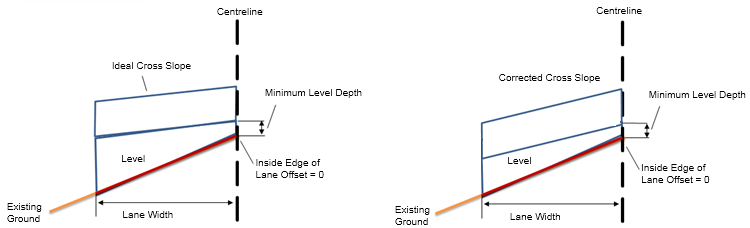
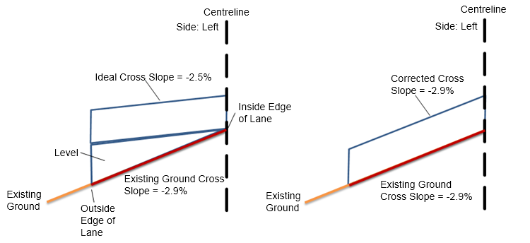
Case 1-2: Ideal Crossfall is greater than Existing Ground Crossfall
| Inputs | |
|---|---|
| Ideal Crossfall | -2.5% |
| Minimum Level Depth | 0 |
| Slope Tolerance | 0.50% |
| Overlay Slope Options | User Defined with Flapping |
| Use Profile Options | Minimum Level Depth |
| Inside Edge of Lane Offset | true (values vary) |
| Outside Edge of Lane Offset | true (values vary) |
| Input | Value |
|---|---|
| Existing Ground Crossfall | -2.9% |
| Existing Ground Crossfall – Ideal Crossfall | -0.4% |
| Slope Tolerance | Existing Ground Slope minus Ideal Crossfall is -0.4%, which is less than the 0.5% Slope Tolerance. |
| Corrected Crossfall | The Corrected Cross slope will be -2.9% |
| Output | Value |
|---|---|
| Corrected Crossfall | -2.9% |
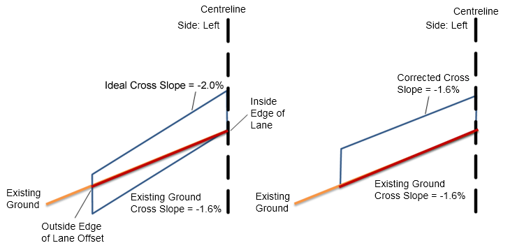
Case 1-3: Ideal Crossfall is less than Existing Ground Crossfall
| Inputs | |
|---|---|
| Ideal Crossfall | -2.0% |
| Minimum Level Depth | 0 |
| Slope Tolerance | 0.50% |
| Overlay Slope Options | User Defined with Flapping |
| Use Profile Options | Minimum Level Depth |
| Inside Edge of Lane Offset | true (values vary) |
| Outside Edge of Lane Offset | true (values vary) |
| Input | Value |
|---|---|
| Existing Ground Crossfall | -1.6% |
| Existing Ground Crossfall – Ideal Crossfall | -0.4% |
| Slope Tolerance | Existing Ground Slope minus Ideal Crossfall is -0.4%, which is less than the 0.5% Slope Tolerance |
| Corrected Crossfall | The Corrected Cross slope will be -1.6% |
| Output | Value |
|---|---|
| Corrected Crossfall | -1.6% |
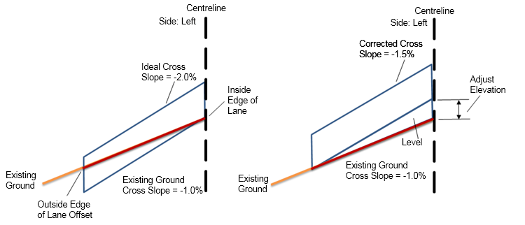
Case 1-4: Ideal Crossfall is less than Existing Ground Crossfall
| Inputs | |
|---|---|
| Ideal Crossfall | -2.0% |
| Minimum Level Depth | 0 |
| Slope Tolerance | 0.50% |
| Overlay Slope Options | User Defined with Flapping |
| Use Profile Options | Minimum Level Depth |
| Inside Edge of Lane Offset | true (values vary) |
| Outside Edge of Lane Offset | true (values vary) |
| Input | Value |
|---|---|
| Existing Ground Crossfall | -1.0% |
| Existing Ground Crossfall – Ideal Crossfall | -1.0% |
| Slope Tolerance | Existing Ground Slope minus Ideal Cross slope is -1.0%, which is greater than the 0.5% Slope Tolerance |
| Corrected Crossfall | The Corrected Cross slope will be -1.5% |
| Output | Value |
|---|---|
| Corrected Crossfall | -1.5% |
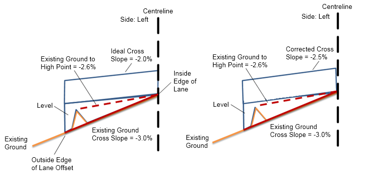
Case 2-1: Ideal Crossfall is greater than High Point
| Inputs | |
|---|---|
| Ideal Crossfall | -2.0% |
| Minimum Level Depth | 0 |
| Slope Tolerance | 0.50% |
| Overlay Slope Options | User Defined with Flapping |
| Use Profile Options | Minimum Level Depth |
| Inside Edge of Lane Offset | true (values vary) |
| Outside Edge of Lane Offset | true (values vary) |
| Input | Value |
|---|---|
| Existing Ground Crossfall | -3.0% |
| Existing Ground Crossfall – Ideal Crossfall | 1.0% |
| High Point Crossfall, measured from Inside Edge of Lane to High Point | -2.6% |
| High Point Crossfall – Ideal Crossfall | -0.6% |
| Slope Tolerance | The Slope Difference between the Existing Ground Cross slope minus Ideal Cross slope result is 1.0%, which is less than the Slope Tolerance of 0.50% |
| Corrected Crossfall | The Corrected Cross slope will be -2.5% |
| Output | Value |
|---|---|
| Corrected Crossfall | -2.5% |
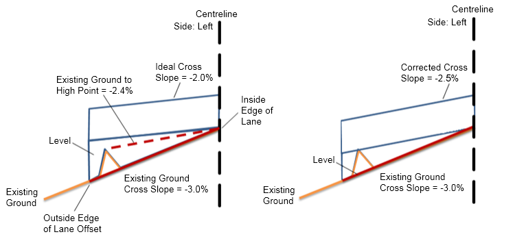
Case 2-2: Ideal Crossfall is greater than High Point
| Inputs | |
|---|---|
| Ideal Crossfall | -2.0% |
| Minimum Level Depth | 0 |
| Slope Tolerance | 0.50% |
| Overlay Slope Options | User Defined with Flapping |
| Use Profile Options | Minimum Level Depth |
| Inside Edge of Lane Offset | true (values vary) |
| Outside Edge of Lane Offset | true (values vary) |
| Input | Value |
|---|---|
| Existing Ground Crossfall | -3.0% |
| Existing Ground Crossfall – Ideal Crossfall | 1.0% |
| High Point Crossfall, measured from Inside Edge of Lane to High Point | -2.4% |
| High Point Crossfall – Ideal Crossfall | -0.4% |
| Slope Tolerance | Existing Ground Cross slope minus Ideal Cross slope is 1.0%, which is greater than the 0.5% Slope Tolerance |
| Corrected Crossfall | The Corrected Cross slope will be -2.5% |
| Output | Value |
|---|---|
| Corrected Crossfall | -2.5% |
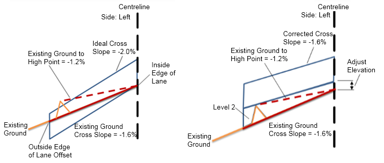
Case 2-3: Ideal Crossfall is less than High Point
| Inputs | |
|---|---|
| Ideal Crossfall | -2.0% |
| Minimum Level Depth | 0 |
| Slope Tolerance | 0.50% |
| Overlay Slope Options | User Defined with Flapping |
| Use Profile Options | Minimum Level Depth |
| Inside Edge of Lane Offset | true (values vary) |
| Outside Edge of Lane Offset | true (values vary) |
| Input | Value |
|---|---|
| Existing Ground Crossfall | -1.6% |
| Existing Ground Crossfall – Ideal Crossfall | 0.4% |
| High Point Crossfall, measured from Inside Edge of Lane to High Point | -1.2% |
| High Point Crossfall – Ideal Crossfall | -0.8% |
| Slope Tolerance | Existing Ground Crossfall minus Ideal Crossfall is 0.4%, which is less than the 0.5% Slope Tolerance. |
| Corrected Crossfall | The Corrected Cross slope will be -1.6% |
| Output | Value |
|---|---|
| Corrected Crossfall | -1.6% |
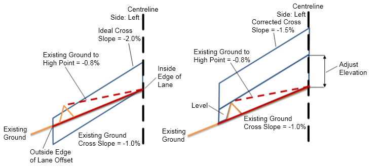
Case 2-4: Ideal Crossfall is less than High Point
| Inputs | |
|---|---|
| Ideal Crossfall | -2.0% |
| Minimum Level Depth | 0 |
| Slope Tolerance | 0.50% |
| Overlay Slope Options | User Defined with Flapping |
| Use Profile Options | Minimum Level Depth |
| Inside Edge of Lane Offset | true (values vary) |
| Outside Edge of Lane Offset | true (values vary) |
| Input | Value |
|---|---|
| Existing Ground Crossfall | -1.0% |
| Existing Ground Crossfall – Ideal Crossfall | 1.0% |
| High Point Crossfall, measured from Inside Edge of Lane to High Point | -0.8% |
| High Point Crossfall – Ideal Crossfall | -1.2% |
| Slope Tolerance | Existing Ground Crossfall minus Ideal Crossfall is 1.0%, which is greater than the 0.5% Slope Tolerance. |
| Corrected Crossfall | -1.5% |
| Output | Value |
|---|---|
| Corrected Crossfall | -1.5% |
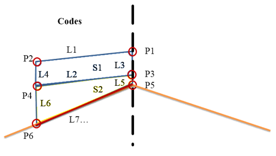
Point, Link and Shape Codes.
The following table lists the point, link and shape codes for this subassembly that have codes assigned to them. Point, link or shape codes for this subassembly that do not have codes assigned are not included in this table.
| Point, Link or Shape | Code | Description |
|---|---|---|
| P1, P2 | EOV | Overlay edges on finish surface |
| P3, P4 | EOV_Overlay | Edges of bottom of overlay |
| P5, P6 | EOV_Levelling | Edges of bottom of level |
| L1 | Top, Pave | Top of overlay |
| L2, L3, L4 | Overlay | Overlay links |
| L5, L6 | Level | For the levelling case |
| S1 | Overlay | Area between the top and bottom of overlay |
| S2 | Level | Area between the top and bottom of level |
| L7 | Existing Ground | Crossfall of the existing ground |
Coding Diagram