Construction Options
![]()
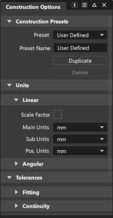
Sets the options that control the modeling of curves and surfaces, including tolerances and units of measure. You can save a collection of construction option settings as a construction preset or they can be predefined by CAD software presets.
Construction presets can be used as pre-defined templates or configurations, which provide a consistent starting point, ensuring that models adhere to certain specifications or design guidelines.
About Construction Presets in Alias 2024 and later
Starting in Alias 2024, Constructions Presets are now included in user preference profiles. By default, they are no longer stored in a separate directory as in previous versions. However, you can export your construction presets to a .json, which you can then use for setting up site-wide construction options.
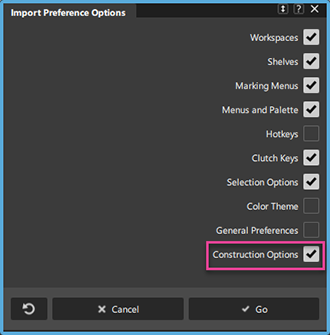
See Workflow - Importing Preferences from a previous version.
About CAD software presets
If you are using a CAD software preset, you cannot change the tolerances. They are locked to the factory settings for the CAD software. You cannot edit or delete the original CAD package presets.
If you want to change a set of presets, use the Duplicate button to create a copy of the set you want to edit, then edit the copy. Changes to the settings in the Construction Options window are always saved automatically.
Construction Options settings
Construction Presets
Copy
Copy the highlighted settings profile to a new profile.
If you want to change some of the settings in one of the presets (for example, Inventor), make a copy of the preset profile, then edit the copy.
Delete
Delete the highlighted settings profile.
You cannot delete the preset settings profiles.
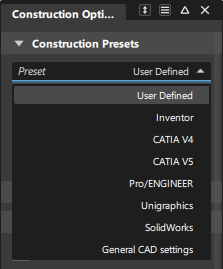
List of settings profiles
Click a profile to use the settings in that profile.
The preset profiles (for example, Inventor) contain the settings needed for best compatibility with various CAD systems.
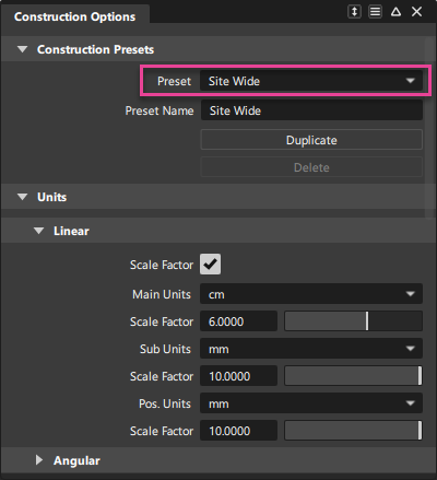
Units
Linear Unit options
Scale Factor checkbox/sliders
Check this box to show Scale Factor sliders for the unit choices (Main Units, Sub Units, and Pos Units).
Use the scale factor sliders to change a unit from whole to fractional or multiple units. For example:
- Set the Sub Units to Inches.
- Set the Scale Factor slider below the Sub Units box to 0.125.
- The sub unit is now eighths of an inch rather than whole inches.
Main Units
The unit of measurement for all linear measurements (in locators, on the promptline and in windows).
Sub Units
The intermediate level of linear units.This is the unit of the second number when you type numbers using the m:s or m:s:p form on the promptline. This unit is only used in keyboard input.
Pos. (positional) Units
The smallest level of linear units. This is the unit of the last number when you type numbers using the m:s:p form on the promptline. This unit is only used in keyboard input.
Angular Unit options
Scale Factor checkbox/sliders
Check this box to show Scale Factor sliders for the unit choices (Main Units, Sub Units, and Pos Units).
Use the scale factor sliders to change the different units from whole to fractional or multiple. For example:
- Set the Sub Units to minutes.
- Set the Scale Factor slider below the Sub Units box to 0.5.
- The sub unit is now half minutes rather than whole minutes.
Main Units
The unit of measurement for all angular measurements (in locators, on the promptline and in windows).
Choose Deg (degrees), Min (minutes), Sec (seconds), or Rad (radians). The default is degrees.
Sub Units
The intermediate level of angular units.This is the unit of the second number when you type numbers using the m:s or m:s:p form on the promptline. This unit is only used in keyboard input.
Choose Deg (degrees), Min (minutes), Sec (seconds), or Rad (radians). The default is minutes.
Pos. (positional) Units
The smallest level of angular units. This is the unit of the last number when you type numbers using the m:s:p form on the promptline. This unit is only used in keyboard input.
Choose Deg (degrees), Min (minutes), Sec (seconds), or Rad (radians). The default is seconds.
Tolerances
Fitting
Curve Fit Distance
The value and units of the maximum distance allowed between two points for the system to consider them coincident (occupying the same space).
- For surface creation tools such as Rail Surface and Square, this value controls the accuracy of the fit of the surface edge to the construction curves.
- For fillet surfaces, this value controls the positional accuracy of the fillet surface.
- For the Stitch tool (used to stitch surfaces into a shell), this value determines which sides to check for gaps. However, the gap is actually checked against the Maximum Gap Distance tolerance (see below). If the gap is within the tolerance, the sides are joined.
Curve Fit Checkpoints
The sampling rate for curve fit constraints such as Continuity Angle and Curve Fit Distance.
Max Surf Spans
The maximum number of spans to create when building surfaces.
- If a rebuild operation on a curve or surface requires adding more than the Max Surf Spans, the operation is cancelled.
- If maintaining continuity requires adding more than the Max Surf Spans, the continuity will not be achieved.
Continuity
Maximum Gap Distance
The maximum distance allowed between two curves or two surfaces for the system to consider them contiguous (touching).
- For the Stitch tool, this value controls whether two edges will be joined when stitching surfaces into a shell.
- For the Surface continuity tool, this value controls whether common edges pass the check for gaps.
Continuity Angle
The maximum angle allowed between two surface normals for the system to consider the normals pointing in the same direction.
A smaller value gives better continuity, but usually requires tools to add more spans to the surface.
Continuity Curvature
The maximum deviation allowed in curvature.
A smaller value gives better continuity, but requires tools to add more spans to the surface.
Topology
Topology distance
Used to calculate which surface is adjacent to which surface when a tool needs to know the topology of the model. This is used by Object Edit > Dynamic Shape Modeling > Transformer Rig, Surface Continuity, and Evaluate > Check Model.
Curve on Surface/Trim
Trim Curve Fit
The maximum deviation allowed between the original curve-on-surface and trim edges.
Max Gap Between Curves
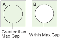
The maximum distance allowed between endpoints of different curves-on-surface for the system to consider them continuous for the purposes of defining a trim region.
In example A, the gap between the two curves-on-surface is greater than Max Gap Between Curves, so the curves do not define an area.
In example B, the gap between the curves-on-surface is within Max Gap Between Curves, so the curves define an area for the purpose of trimming.
Rational Flags
Primitives
Create new primitives using rational geometry.
Curves
Create new keypoint curves and circle primitives using rational geometry.
Fonts
Default Modeling Font Size
Choose a value from the pop-up menu to adjust the size of the font used in the modeling windows for annotations and such text.
Text Display Mode
Choose either Scale or Fixed Size. Fixed size will display at a constant size; Scale will change based on Dollying and Zooming.
Use the tolerances required by a specific CAD package
Use the Construction Options to set the tolerances enforced by the modeling tools. The requirements for transfer to specific CAD packages are available as presets.
Set up tolerances for transfer to a specific CAD package
Open the Presets section.
Choose one of the settings profiles from the list:
Click the CAD software you want to model for. This sets the construction options to values needed for maximum compatibility with that CAD package.
Click General CAD Settings if the CAD package that you want to model for is not on the list. This sets the construction options to generic CAD values that will be compatible with most CAD packages.
Click User Defined to set the construction options manually.
Tip: You cannot edit the presets of the CAD packages in the list directly. Select the name of the CAD package and click Copy to create a new profile you can edit.
Create a set of custom tolerances
Open the Construction Presets section of the Construction Options window.
Choose one of the settings profiles from the list:
- If the settings you want to add are very similar to one of the preset CAD packages, click the name of the CAD package.
- Otherwise, click User Defined.
Click Copy.
Double click the new profile to rename it.
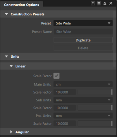
Set up site-wide construction presets
![]()
You can copy a construction presets file to a shared network location so that it can be used for site-wide construction presets. Note that these presets will not be modifiable by others.
Set the options you want for all users in the Construction Options window.
Select the new construction preset to make it active.
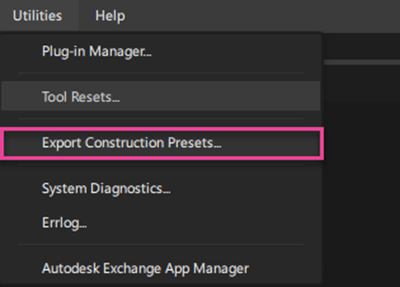
Export the construction presets to a .json by selecting Utilities > Export Construction Presets.
By default, the file gets saved to the
C:/Users/username/Autodesk/Alias/Profilesdirectory, but you can choose any location.Copy this file to a shared network location so that all users can access the same construction presets. (See Access site-wide construction presets on a network).
Open the ConstructionPresets.json file (the copy, not the original) in a text editor, and change the names of the presets so that they are unique and do not duplicate names from the original file. You can also make the following edits to the file:
- Specify the default preset that gets loaded in the Construction Options when Alias starts by editing the
"Default preset"flag. - If you want the standard default construction presets to be visible in the Construction Options, set
"Show standards"totrue, otherwise set it tofalse.
For more information about the ConstructionPresets.json file, see Export Construction Presets.
- Specify the default preset that gets loaded in the Construction Options when Alias starts by editing the
Access site-wide construction presets on a network
If your administrator has placed the construction presets file in a shared network location, follow these steps to access it:
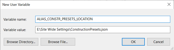
Set environment variable ALIAS_CONSTR_PRESETS_LOCATION to the network location (path) where the site-wide construction presets file is located.
Start Alias.
The construction option settings default to those in the construction presets file on the network. These construction presets cannot be edited
If the administrator changes the construction presets file on the network, each user must re-start Alias to see the changes in the Check Model and Construction Options windows.