History Visualizer
![]()
Opens the History Visualizer, which displays the construction history of objects in your scene as a node graph of connected input geometry, tool commands, and output nodes.
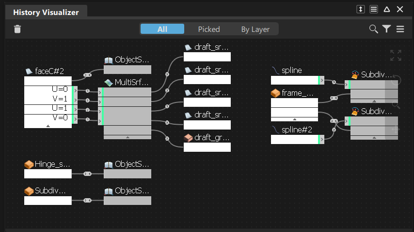
Input geometry, tools, and the output of tool commands display in the graph area as a series of connected nodes. Construction history flows left to right from the input geometry nodes along the connections to the tool nodes, and then to the output nodes resulting from commands.
See Construction history and metadata for information about construction history.
History Visualizer icon bar
![]() - Suspend History - Suspends construction history updates for picked objects. (also available in the context menu).
- Suspend History - Suspends construction history updates for picked objects. (also available in the context menu).
![]() - Delete Selected - Deletes the selected construction history and leaves the input geometry unchanged. This does not delete the actual objects. It is the same as picking the object and choosing Delete > Delete Construction History.
- Delete Selected - Deletes the selected construction history and leaves the input geometry unchanged. This does not delete the actual objects. It is the same as picking the object and choosing Delete > Delete Construction History.
![]() - Displays the history graph of all the objects in the scene (also available in the More menu).
- Displays the history graph of all the objects in the scene (also available in the More menu).
![]() - Displays the history graph of picked objects (also available in the More menu).
- Displays the history graph of picked objects (also available in the More menu).
![]() - Focuses the graph view based on the layers selected in the Object Lister or Layer Bar. For example, selecting a layer automatically focuses the graph view on nodes in the selected layer (also available in the More menu).
- Focuses the graph view based on the layers selected in the Object Lister or Layer Bar. For example, selecting a layer automatically focuses the graph view on nodes in the selected layer (also available in the More menu).
![]() - Filter - Lets you filter the graph view by node type, such a tool node or input node. When you load a WIRE file, the History Visualizer populates a list of tool nodes contained in the file. By default, all of the nodes are on for filtering. To focus the view on a specific tool node, turn off the filtering for all other tool nodes. See Workflows: Basics.
- Filter - Lets you filter the graph view by node type, such a tool node or input node. When you load a WIRE file, the History Visualizer populates a list of tool nodes contained in the file. By default, all of the nodes are on for filtering. To focus the view on a specific tool node, turn off the filtering for all other tool nodes. See Workflows: Basics.
- Settings - Access the Settings menu. See History Visualizer Settings menu.
![]() - More - Access the History Visualizer More menu. See History Visualizer More menu.
- More - Access the History Visualizer More menu. See History Visualizer More menu.
![]() - Fit Window - Adjusts the width of the graph view so that all node connections from left to right get displayed. Depending on the complexity of the history graph, some nodes may not be visible (also available in the Settings menu).
- Fit Window - Adjusts the width of the graph view so that all node connections from left to right get displayed. Depending on the complexity of the history graph, some nodes may not be visible (also available in the Settings menu).
![]() - Reset Node Layout - Resets the graph view to the default node layout (also available in the Settings menu).
- Reset Node Layout - Resets the graph view to the default node layout (also available in the Settings menu).
![]() - Zoom View - Click-drag on the icon to zoom the view. Drag to the right or upwards to zoom in, left or downwards to zoom out.
- Zoom View - Click-drag on the icon to zoom the view. Drag to the right or upwards to zoom in, left or downwards to zoom out.
![]() - Pan View - Click-drag on the icon to pan the view. The panning direction follows the mouse.
- Pan View - Click-drag on the icon to pan the view. The panning direction follows the mouse.
History Visualizer Settings menu
Fit Window - Adjusts the width of the graph view so that all node connections from left to right get displayed. Depending on the complexity of the history graph, some nodes may not be visible (also available in the icon bar).
Reset- Resets the graph view to the default node layout (also available in the icon bar).
Compress Outputs - Reduces the display of output nodes from each tool node to a single, compressed node. Use this to keep the workspace neat and optimize available space.
Collapse All - Collapses the input and tool nodes view so that each node displays a single connection. Nodes with more than one input or output connection are labeled with Multiple connections. Use this to keep the workspace neat and optimize available space. Click the caret at the bottom of a node to toggle between collapsed and expanded view.
Expand All - Returns the view of all nodes to the expanded view, which is the default setting.
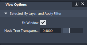
View Options - Lets you configure the graph view so that it automatically zooms to filtered nodes while dimming the display of other nodes in the graph. Turn on Fit Window to apply automatic zooming. Use the Node Tree Transparency slider to adjust the dimming of unfiltered nodes and node networks. The View Options apply when filtering nodes by tool node, By Layer, and All. Fit Window is on by default.
Pan With MMB - When on, you can pan left, right, up, or down in the graph by holding down the middle-mouse button and dragging. This is the same as using the Pan View tool.
Hide Window on Replace - When on, the History Visualizer window closes after executing a Replace input command. See Workflow: Modify history by replacing inputs.
History Visualizer More menu
Suspend Global - Suspends construction history updates for all objects.
Suspend Selected - Suspends construction history updates for picked objects (also available in the context menu).
Resume Global - Resumes construction history updates for all objects.
Resume Selected - Resumes construction history updates for selected nodes (also available in the context menu).
Replace Selected Inputs - Lets you replace one or more inputs to a tool node (also available in the context menu).
To see which nodes get affected when replacing multiple inputs to a tool node, right-click the node and hover over the Replace command in the context menu.
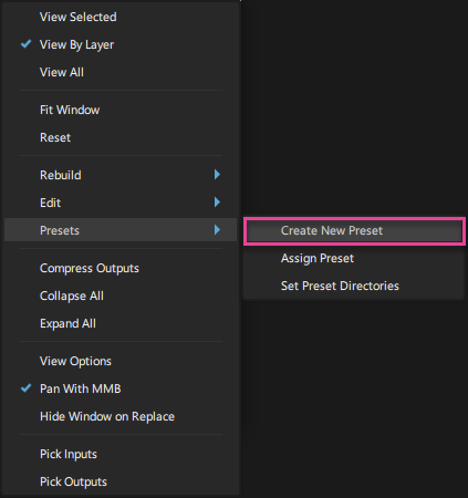
Create New Preset - Creates a preset of the selected tool node's construction history. Presets can be applied to tool nodes of the same type. When you create a preset, it gets saved to the designated preset directories as a .hpreset file.
Access this option while working in the graph view by right-clicking and selecting Create New Preset from the menu that appears (also available in the context menu).
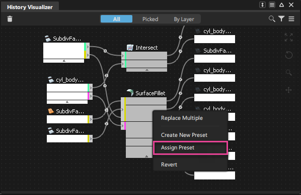
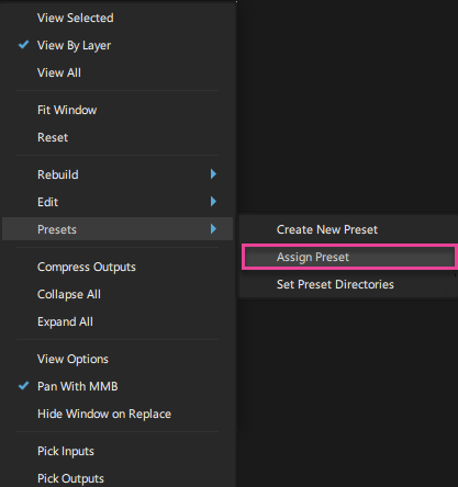
Assign Preset - Assigns a history preset to the selected tool node. Access this option while working in the graph view by right-clicking and selecting AssignPreset from the menu that appears (also available in the context menu).
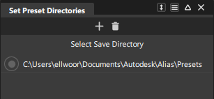
Set Preset Directories - Opens the Set Preset Directory window where you can specify directories for storing preset (.hpreset) files. By default, a preset directory is automatically created the Alias directory. For example:
\Documents\Autodesk\Alias\user_data\Presets.You can add a remove preset directories. They can a local or network locations, but at least one preset directory must be specified at all times. After adding a new preset directory, you can designate it as the location which new presets get saved.
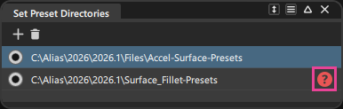
Note: Invalid preset directory paths are flagged with an icon in the Set Preset Directories window. If a previously set preset directory path is broken or the directory no longer exists, click the icon to either browse to the new directory location or remove it from the list.
Pick Inputs - Pick the objects used as inputs to create the selected operations (also available in the context menu).
Pick Outputs - Pick the objects created by the selected operations (also available in the context menu).
Query Edit - Opens the control options of the selected command node to display its construction history (also available in the context menu).
This is the same as selecting Query Edit, and then selecting an object.
Revert History - Select this to undo and remove history from selected tool nodes and revert any edits applied to the input geometry by the tool node. Use this option to undo and remove history on multiple tools nodes at the same time. Access Revert History while working in the graph view by right-clicking and selecting Revert from the context menu that appears.
Delete Selected History - Deletes the selected construction history and leaves the input geometry unchanged (also available in the context menu).
This does not delete the actual objects, only the construction history being maintained (the same as picking the object and choosing Delete > Delete Construction History).
Workflows: Basics
Working in the graph window
By default, the History Visualizer displays a graph view of the construction history for all the objects in the file. Only objects with construction history appear in the graph.
Ways of viewing objects with history
Use the All, Picked, and By Layer buttons at the top of the graph window to focus view.

Navigating in the graph
Use the tools on the right side of the graph window to navigate inside the window.
Selecting and moving nodes
- Click a node to select it, or box-select nodes, than drag to move them in the graph.
- To move a tool node and its connected input and output nodes as a group, click the tool node, and then press Ctrl and drag.
- To zoom the viewport focus to the geometry that a tool node is operating on, Alt + click the tool node. This works similar to the Look At tool.
- To select a node and all its connected nodes, Shift + click it.
When selecting nodes in the graph, note that:
- Input nodes: Highlights the node and its connections to the tool node. The input geometry is picked in the viewport.
- Tool nodes: Outlines the connected input and output nodes. The object created by the tool operation is picked in the viewport
Modify construction history
Update tool node settings
Trigger a query edit by doing one to the following:
- Double-click a tool node.
- Select the tool node, and then select Query Edit from the More menu.
The tool control window opens from which you can modify the tool settings.
Revert or delete history
No objects are deleted in the viewport when you revert or delete history.
Revert history - Revert History removes history and reverts any updates the tool made to the geometry.
In the graph, select a tool node and do one of the following:
- Right-click and select Revert History from the context menu.
- Select Revert History from the More menu. Tip: You can revert history on multiple nodes by box selecting the nodes, and then selecting Revert History from the More menu.
Delete history - Delete History removes the history and keeps the updates the tool made to the geometry. Select the node and click the
 icon or select Delete Selected History from the More menu.
Suspend and resume history
Use the options in the Rebuild options from the More menu to suspend and resume all or selected tool nodes. You can also click the Suspend History icon in the toolbar.
Working with nodes
Filter the view by node type
Click the Filter icon ![]() and choose nodes and node networks of interest. When a filter is on, the graph view automatically zooms to these nodes and associated networks, while dimming the display of other nodes in the graph. Filtering the graph view helps you isolate nodes for applying presets, replacing inputs, or reverting history.
and choose nodes and node networks of interest. When a filter is on, the graph view automatically zooms to these nodes and associated networks, while dimming the display of other nodes in the graph. Filtering the graph view helps you isolate nodes for applying presets, replacing inputs, or reverting history.
Manage the workspace
There are several way to arrange nodes in the History Visualizer workspace to keep it neat and make best use of the available space.
Collapse and compress nodes
To:
- Collapse an individual input or tool node - Click the triangle icon (
 ) below it. When collapsed, a node's input and output connections display with a single connection and the nodes are labeled with Multiple connections.
 - Collapse all the tool nodes, select Collapse All from the More menu.
- Expand all collapsed tool nodes, select Expand All from the More menu.
- Group output nodes from a given tool to a single node, select Compress Outputs from the More menu.
Align nodes
You can align nodes vertically in the graph.
Drag a node toward the node directly above it until a green spacer appears, then the release it.
The node snaps into vertical alignment with the one above it.
Workflow: Modify history by replacing inputs
You can modify the construction history of an object by substituting the connected input nodes of geometry with other geometry in the scene. The promptline assists you in selecting valid input geometry to make the replacement.
Replace a single input
Do one of the following:
- Right-click the input node port on the tool node and select Replace from the context menu.
- In the viewport, select the replacement geometry.

Or
- Right-click the input node and select Replace from the context menu.
- In the viewport, select the replacement geometry.
Replace multiple inputs
You can replace multiple inputs to any multi-surface tool, such as the Surface Fillet or Freeform tool.
Do one of the following:
- Right-click the tool node and select Replace Multiple from the context menu.
- In the viewport, select the replacement geometry and rebuild.
Or
- Shift + select input nodes you want to replace.
- Right-click and select Replace Multiple from the context menu.
- In the viewport, select the replacement geometry and rebuild.
Workflow: Create and assign construction history presets
Presets save the construction history of existing tool nodes, which you can then apply to other tool nodes of the same type. Using presets lets you quickly and consistently regenerate commonly used geometry.
See About construction history presets for more information about presets.
Set file locations for presets
Before creating history presets, you can set a file location to store them. By default, Alias automatically creates a Preset directory in the C:\Users\username\Autodesk\Alias folder.
Initially, all presets you create are saved to this default preset directory.
You can add more local or network file locations as preset directories, and set one of these directories as the designated location for saving presets. You can apply presets from any directory you add as preset directory.
To add a file location as preset directory, select Set Preset Directories from the More menu.
Click the Add Directory
 icon, and then browse to the location you want to set as a preset directory.
To set it as the designated preset directory, click to the left of the new file location.
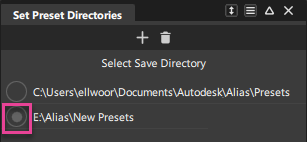
All new presets will be saved to this location.
To remove a preset directory, either right-click and select Remove. Or, select it, and then click the Remove Selected icon
.Note: Invalid preset directory paths are flagged with an icon in the Set Preset Directories window. If a previously set preset directory path is broken or the directory no longer exists, click the icon to either browse to the new directory location or remove it from the list.
Creating history presets
In the history graph, locate the tool node with the history you want to save as a preset.
Tip: Use the graph view filter options to quickly locate the tool node you want to create presets from. For example, you can filter the graph view by tool node type so that it focuses on only the tool nodes you specify.Do one of the following:
Right-click the node and select Create New Preset from the context menu.
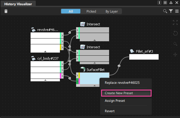
Choose Create New Preset from the More menu.
Type a name for the preset and click save.
Your preset is saved as a
.hprestfile in the designated preset directory. By default, the designated directory is located here:C:\Users\username\Autodesk\Alias\Presets.
Assign a history preset
In the history graph, locate the tool node to which you want to assign a history preset.
Do one of the following:
Right-click the node and select Assign Preset from the context menu.
Choose Assign Preset from the More menu.
The Presets window displays the presets contained in the designated directory.
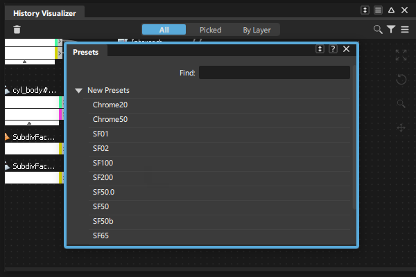 Tip: Use the Find field to quickly find a preset. As you begin typing, the Preset list automatically populates with results based on your query.
Select a preset to apply.
Note: If you receive an error after assigning a preset, it means that a preset contains property values that are incompatible with the input geometry. Check the promptline message for more information (see Prompts and Go buttons). Then, select a compatible preset to assign.
About construction history presets
History presets provide a way to save and reuse Alias tool settings. Presets save the construction history of existing tool nodes, which you can then apply to other tool nodes of the same type.
Using presets lets you quickly and consistently regenerate commonly used geometry. Sharing presets across a network not only helps your design team to increase workflow efficiency, but also they can help maintain surface modeling standards across teams.
About history presets
What is required to create a preset?
You can create history presets from tool nodes that have active construction history. The tool node must be currently in the History Visualizer graph before it can be the source of a history preset. After you create a history preset from an active tool node, the preset is independent of its source tool node.
What does the preset contain?
Presets contain all the tool node's active construction history, meaning all the tool settings used to generate the output geometry. Information about the input geometry connected to the source tool node is not captured in the preset.
What can a preset be applied to?
You can apply history presets to tool nodes that have active construction history and are of the same type as the source tool node. For example, you can only apply a history preset that was created from a Surface Fillet tool node to another Surface Fillet tool node.
Which tool nodes support History Presets?
You can create a History Preset from the following tools:
| Surface tools | Surface Rolled Edge tools | Curve tools | Transform tools | Object Edit tools |
|---|---|---|---|---|
| Revolve | Fillet Flange | Curve & COS Offset | Array | Align |
| Skin | Tube Flange | Freeform Curve Blend | Path Array | Align 2008 |
| Rail Surface | Tubular Offset | Curve Fillet | Surface Array | |
| Profile | Panel Gap | |||
| Square | ||||
| Surface Fillet | ||||
| Symmetric Fillet | ||||
| Freeform Blend | ||||
| Profile Blend | ||||
| Multi-Surface Draft | ||||
| Corner Blend | ||||
| Stitch and Seam | ||||
| Surface Offset | ||||
| Project |