Control Panel
![]() +
+ ![]()
Shows or hides the Control Panel. The Control Panel provides access to some of the key settings and features that apply across NURBS and Subdiv modeling, such Parameterization, Controls Display, and Curvature display.
RMB + click a collapsed section to access its options in fly-outs. This allows you to quickly access the options without expanding the section, while keeping the Control Panel compact saving screen-space.
At the top of the Control Panel is the Pick list, which isolates a single curve or surface from a collection of curves and surfaces. The white text field displays the name of the picked component.
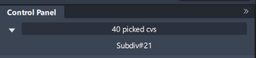
When you pick more than one object, the gray text box tallies all picked (and active) components in the modeling space. To view a drop-down list of all selections, and to switch between components, click and hold on the gray text box.
Related videos
Parameterization
The rebuild tool can work with several curves or surfaces at a time. The Control Panel indicates "# picked curves" or "# picked surfaces". If the objects have a different degree or number of spans in U or V, the corresponding field is blank.
About changing the degree or number of spans on curves and surfaces
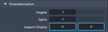
Use the Degree and Spans options to change the degree or number of spans of the picked curves and surfaces.
This rebuild tool can work with several curves or surfaces at a time. The Control Panel indicates "# picked curves" or "# picked surfaces". If the objects have a different degree or number of spans in U or V, the corresponding field is blank.
For a surface, changing the degree or number of spans in one direction (U or V) does not affect edges running in the other direction.
Change the degree or number of spans on curves and surfaces
Pick the curves or surfaces whose degree or spans you want to modify.
Note: If your selection includes both curves and surfaces, the Control Panel indicates number of picked objects but does not let you enter values for Degree or Spans.Edit the Degree or Spans fields in the Control Panel in the following ways:
- Type a new value in the field, then press Enter.
- Click the arrowhead to the right or left of the number.
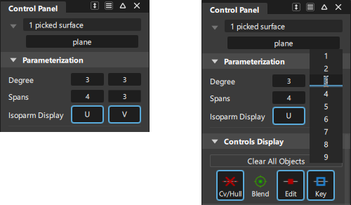
- Click in the field and choose a value from the vertical number list that appears.
- MMB click and then drag the double-head arrow that appears.
For surfaces, the leftmost fields represent the degree or spans in the U direction, and the rightmost fields the values in the V direction.
When a value is modified, the geometry (and attached evaluation locators) update to show the changes. The maximum deviation between the old and new geometry is displayed on the promptline.
Two buttons appear in the active window.
Do one of the following:
- Click Accept to use the modified objects.
- Click Cancel to return to the original objects. Choosing a different tool without clicking any of the buttons, or deselecting the geometry also cancels the changes.
Controls Display
For a better view of your design, the Display options let you display or hide the following items on the picked geometry:
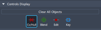
Click the Cv/Hull button to Show CVs on picked objects. If CVs are not displayed, clicking on the object(s) while inside the Transform CV tool automatically turns on all CVs and hulls. As soon as you choose a different tool, the CVs and hulls are turned off again.
Curvature
Checks curvature on curves and surfaces with a combs and radius values.
Select the curve or surface you want to check, and then click either U or V for Comb Display.
The curvature comb displays.
Use the controls in the Curvature section to adjust the comb display.
To delete the locator, click the U or V icon again or select Delete > Locators.
Curvature combs can also be displayed on a surface cross sections through the Cross Section Editor options. See Windows > Editors > Cross Section Editor.
To view a surface curvature as a color map on the surface, use the Curvature Evaluation mode under Diagnostic Shading on the Control Panel.
See Curvature Evaluation.
Curvature options
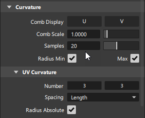
Comb Scale
This option scales the length of the curvature combs.
It also applies to the curvature combs on cross sections.
Invert Comb
![]()
Flips curvature combs from above to below the curve and back again. Use this option instead of setting a negative Comb Scale value or using the Alt key to drag values below 0.
Samples
The sampling density per curve, which is the number of quills on a curvature comb. Increasing the samples results in a finer curvature comb.
This option also applies to the curvature combs on cross sections.
Spacing
This option only applies to surfaces.
Length – Evenly space the curvature combs along the length of the surface (in U or V direction). The numbers of combs (for U and V respectively) are given by the values typed in the Number text fields.
Parameter – Place the curvature combs only on isoparametric curves (in U and V direction).
Number
Set the number of curvature combs on the surface in each direction.
Radius Min/Max
Click the check boxes to turn on or off locators displaying the points of Minimum and Maximum radius of curvature. These correspond to the points of maximum and minimum curvature respectively.
Show Absolute
Check this box to show only the absolute minimum and maximum radii over all the curvature plots in U and/or V. This option only applies when at least one of Radius Min or Radius Max is checked on.
Transparency
This set of options lets you control the level of transparency of geometry and other items such as locators and canvases. Transparency is achieved by blending the object color into the background color.
![]()
Quality
This set of options lets you adjust the display of your curves, surfaces, and meshes. However, it only affects the visual display of the geometry, not the geometry itself.
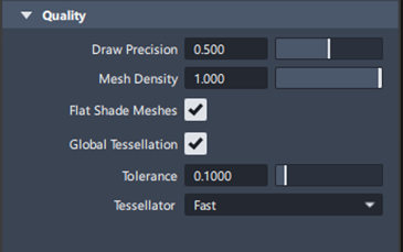
Draw Precision
Use this to control the drawing smoothness of all curves and surfaces. The slider value goes from 0.0 (rough approximation) to 1.0 (very smooth). The default is 0.5.
This value applies to all existing curves and surfaces, as well as all new curves and surfaces created from this point on.
Mesh Density
Use this slider to control which percentage of the triangles are displayed. By default, the slider is set to 1.0 (all the triangles are drawn). Drawing less triangles increases performance speed.
Flat Shade Meshes
When this option is turned on, flat shading is applied to the mesh when using one of the diagnostic shading modes. Each triangle is rendered in a single color, producing a faceted effect.
Global Tessellation
![]()
Sets the tessellation values for visualization globally throughout Alias.
When turned on, the Tessellator and Quality settings in the Hardware Shade window and the Tolerance and Tessellator settings in the Diagnostic Shade window are not available. This affects both the VRED Renderer and Alias Renderer when using Hardware Shade.
- Tolerance - Controls how accurately surfaces are tessellated when Quality is set to User defined. The slider range is 0.001 to 0.1 cm. The default value is 0.005 cm.
- Tessellator - Select Fast for quicker, but less accurate tessellation. Select Accurate for slower, accurate tessellation.