Cross Section Editor
The Cross Section Editor is used to create, apply and manage visual cross sections on surface and mesh geometry. The sections are calculated on the tessellated geometry so that they update responsively as modifications are made, providing valuable interactive feedback.
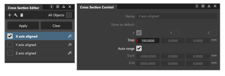
The editor contains three preset cross section groups, perpendicular to the X, Y, and Z axes at 100 mm intervals. The interval size can be modified by the user. Additional section types can be created and added to the list and are stored with the model.
The editor has a separate Control window for adjusting each cross section settings (accessed by a double-click on the cross section name).
Editor icon bar
![]()
![]() New - Lets you define sections in five different ways: Axis Increment, Axis Discrete (choice of X, Y or Z), Picked Reference, Planar, or Radial. Choosing one of these options creates the cross section group, applies the cross section group to the selected geometry (or all geometry if All Objects is turned on) and opens the appropriate option window.
New - Lets you define sections in five different ways: Axis Increment, Axis Discrete (choice of X, Y or Z), Picked Reference, Planar, or Radial. Choosing one of these options creates the cross section group, applies the cross section group to the selected geometry (or all geometry if All Objects is turned on) and opens the appropriate option window.
![]() Tools - Promote - Create copies of selected cross sections as either section data or degree 1 NURBS curves. You can also pick individual sections after you enter the Promote tool. Shift-select Promote or click the
Tools - Promote - Create copies of selected cross sections as either section data or degree 1 NURBS curves. You can also pick individual sections after you enter the Promote tool. Shift-select Promote or click the  icon to open the Promote Options:
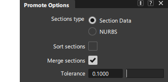
Section Type - Choose to create section data or degree 1 NURBS curves.
Sort Sections - If this option is checked on, the X, Y, and Z sections are placed in separate color-coded layers. All other sections are assigned to a layer called Other sections.

Merge Sections - If this option is checked on, cross sections that are position (G0) continuous, and belong to the same intersecting plane, are merged into a single section curve. The Topology Distance tolerance from the Construction Options is used to determine if sections should be merged.
Tolerance - Fitting tolerance used to rebuild the internal NURBS curves as section data.
![]() Tools - Dynamic Section - Shortcut for the Dynamic Section tool. See Evaluate > Dynamic Section for options and usage.
Tools - Dynamic Section - Shortcut for the Dynamic Section tool. See Evaluate > Dynamic Section for options and usage.
![]() Delete - Deletes cross sections from the editor list, and clears those sections from geometry in the scene.
Delete - Deletes cross sections from the editor list, and clears those sections from geometry in the scene.
All - Delete all cross section groups except the preset X-axis, Y-axis and Z-axis groups, which cannot be deleted.
selected - Deletes only the selected cross section group(s).
To select sections, click on the cross section name in the list to highlight it with a blue background. Use
CtrlandShiftto select more than one section. Selection is not affected by the checkmark being on or off.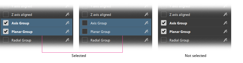
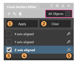
All Objects 

Turn on All Objects (check mark) to apply the selected section groups to all visible geometry (surfaces and meshes).
If you turn off All Objects (no check mark), any new section group you select is only applied to the picked (active) geometry.
List item tools
Choosing All Objects On/Off will affect how the following list icons and editor buttons work.
Apply Button - (All Objects Off only.) Click the Apply button to apply the selected cross section groups to newly selected geometry.
Clear Button - Remove the display of cross sections from the geometry, and de-selects then in the editor. The cross sections definition remains in the editor, so they can be re-applied.
- All Objects Off: Clears cross sections from the selected objects. If nothing is selected, all cross section groups are cleared from all geometry.
- All Objects On: Clears cross sections from all objects.
Apply Checkbox - Applies the cross section to the geoemtry.
- All Objects Off: Applies the cross sections to selected objects only.
- All Objects On: Applies the cross sections to all objects.
- Multiple cross sections can be applied by selecting the checkmark on additional cross section groups in the list.
Name field - Exclusive Apply & open control window
- Clicking once on the name field will apply the section to either the selected objects (if All Objects is off) or all objects (if All Objects is on). The checkmark will also be activated.
- Clicking on an alternative cross section name will will apply that section, and clear any previously applied sections. Useful for swapping between different sections.
- Clicking on the name, and then deselecting the checkmark will leave the section as selected but not applied.
- Double-click on the name to open the Cross Section Control window for that section:
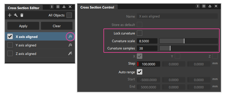
Curvature display


- Turns on or off the curvature comb applied to each cross section group on the geometry.
- Double-click on the cross section name to open the Control window to modify the curvature display settings. Note, these are not displayed if the curvature is turned off.
- Use Lock curvature to prevent accidental modification of the cross sections curvature combs when using the Control Panel > Curvature settings for Comb Scale or Samples.
- Note: If the curvature comb appears to not be smooth, you may need to adjust the tessellation slider in the Diagnostic Shade Panel to get an accurate display.
Workflow - Applying cross sections to geometry
Cross section accuracy / tessellation
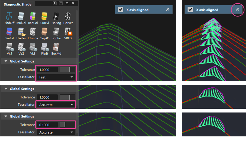
Cross sections are visual curves calculated on the tessellated version of the surfaces. This enables fast updates of the sections whilst moving CVs to provide interactive modeling feedback.
The Diagnostic Shade Panel Tolerance and Tessellator settings control the accuracy (smoothness) of visual cross sections (and curvature combs if applied).
Use a lower tolerance value and set the tessellator to Accurate instead of Fast for smoother and more accurate cross sections. This will increase calculation times however and may affect interactive performance on large models. Avoid using All Objects On if calculation times are too slow, and only apply cross sections to the geometry you are focussed on.
![]()
Cross sections and Construction Planes
When you set or toggle to a construction plane, Axis Increment (X, Y, Z) sections are re-drawn to match the new coordinate system. These are restored to the match the world axes when the World Construction Plane is returned to.
Other section types (discrete, planar, radial) maintain their original location regardless of the set Construction Plane.
Cross section display
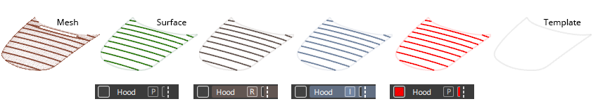
The color of the cross sections will reflect the geometry type and the layer state. Templated items do not display the applied cross sections.
Wireframe anti-aliasing applies to visual cross sections. Turn anti-aliasing on and off through Display > Anti-Alias > Wireframe Anti-Alias.
The line thickness of the cross sections can be set to single or double in the Visual Curves (Cross Sections) of Display > Draw Style.
Create smooth NURBS curves from cross sections
To create NURBS curves degree 2 and above from the section data, use the Curve Edit > Fit Curve  tool to build a new curve to match the section data within your required tolerance.
Degree 1 curves can be created using the Promote tool in the Cross Section Editor icon bar.
Snap and measure to visual cross sections
The following objects will automatically snap to the visual sections when you position them by clicking a section:
- Blend points
- Point-of-interest (when tumbling)
- Construction objects (points, vectors, construction planes)
You can also snap the following objects to visual sections by holding down the Ctrl and Alt keys and clicking a section:
- Control vertices
- Edit points
- Pivot point
In addition, the following measurement tools work on visual sections:
- Show deviation from the Control Panel
- Locators > Annotate
- Locators > Measure > Distance
- Locators > Measure > Angle
- Locators > Deviation > Closest Point
- Locators > Deviation > Curve to Curve
- Locators > Deviation > Curve to Surface
Modifying surfaces with visual cross sections causes those sections to update, in turn causing the measurement locators to update.
Clearing a visual cross section group, or modifying its definition (through the control window) deletes the associated measurements.
The pick chooser appears when selecting overlapping visual cross sections to create measurements.
Workflow - Creating additional Cross Section Types
Use the ![]() icon on the icon bar to create a new cross section. The control window will open with options for the new section.
icon on the icon bar to create a new cross section. The control window will open with options for the new section.
All new cross section types share the following options in the control window:
Common settings
- Name - Shows the name of the cross section group that appears in the Cross Section Editor. Double-click this field to change the name.
- Store as default - Check this option to create a default section group (in addition to the X, Y, and Z section defaults). The cross section group can then be applied across stages or across sessions. It remains in the Cross Section Editor until explicitly deleted.
![]()
New Axis Increment
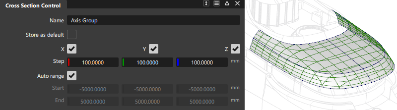
These cross sections are perpendicular to the X, Y, and Z axes and are evenly spaced. They are the same as the three default sections, but x,y and z sections can be grouped in one cross section set. They start from the origin and extend in both directions.
- X/Y/Z - Turn on or off to view various combinations of cross sections perpendicular to the X, Y and Z axes.
- Step - The spacing between cross section lines along the X, Y, and Z axes.
- Auto range - If this option is checked, the bounding box of the picked objects is used to determine where to compute the cross sections, so that they show over the whole geometry independently of its position in space.
- Start/End - These options are only available when Auto Range is off. The three fields represent the X, Y, and Z coordinates for the start and end of the range over which the cross sections are drawn. If Start equals End, a single cross section line is created.
![]()
New Axis Discrete
These are individually-created cross sections that lie in a plane perpendicular to the X, Y or Z axis at a specific location. That X, Y or Z location is specified through the control window or by clicking the mouse.
Section location - Use this field to enter the location for a discrete cross section. The new value is added to the list below and the field is reset to 0.0. A locator corresponding to the location is created on the model. Double-click a value in the list to change it.
Delete- Click on a location in the list (the field turns blue and the locator is selected). Then click the Delete button to remove the corresponding cross section.
![]()
New Picked Reference
Cross sections are created at the intersection between the geometry and selected section data or construction planes.
- Number of references - This field displays how many planes or sections have been selected as references.
![]()
New Planar

Cross sections are created at the intersection between the geometry and a (temporary) construction plane generated on the fly using the same interaction as the Construction Plane tool. You can also select an existing construction plane.
Number of planes - The number of cross sections created. The first one corresponds to the intersection of the construction plane with the surfaces. Additional cross sections are created in the direction of +Z axis of the construction plane, at Step size intervals.
Step size - The spacing between the cross sections.
Mirror planes - If checked, cross sections are created on both sides of the defining plane. (For example, if Number of planes is set to 3, and Mirror planes is on, the total number of sections will be 5).
![]()
New Radial
Cross sections are created perpendicular to the tangent of a selected curve or edge, equally spaced by arc length. The driving curve can be a free curve, a curve-on-surface, or a surface edge or isoparm.
- Number of planes - Number of planes to define along the driving curve(s). The cross sections are created where the planes intersect the geometry. The default is 10.
- Chain selection - If this option is checked, selecting a driving curve also selects all other curves that are tangent continuous with it.