Use this dialog box to describe the allowable variation from nominal geometry.
|
Symbol tab |
|||
| Options
Provides reference line options. |
|||
|
Reference Line List the positions where the reference line attaches to the tolerance indicator frame. |
|||
|
Top frame Specifies the top position where the reference line attaches to the tolerance indicator frame. This option is available only in ISO 1101:2017(E) revision.
 |
|||
|
Bottom frame Specifies the bottom position where the reference line attaches to the tolerance indicator frame. This option is available only in ISO 1101:2017(E) revision.
 |
|||
|
Requirements Contains buttons and edit boxes to specify the variations. These are named only in tooltips. Move the pointer over them to identify them. |
|||
|
Insert symbol Displays a palette enabling you to insert a special character at the current cursor position. The preview in the drawing area shows the special character while the dialog box shows the corresponding control key sequence. |
|||
|
Top Notes Specifies text that must display above the feature control frame. In the drawing area the notes and the feature control frame move together as a single entity. |
|||
|
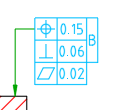
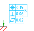
Geometric symbol Displays a list of symbols to enable you to specify the geometric characteristic for which you are defining the tolerance. The symbols on this list depend on the current standard. |
|||
|
Tolerance 1 Specifies primary tolerance data. Use the Insert symbol list to insert special characters such as the diameter symbol or the maximum material condition symbol. |
|||
|
Tolerance 2 Specifies secondary tolerance data. This option is available only for the ANSI standard. |
|||
|
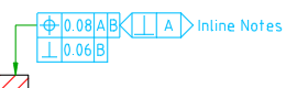
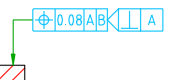
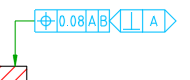
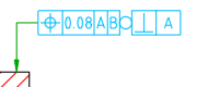
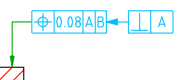
Datum 1 Specifies the primary datum from which the tolerance is measured. |
|||
|
Datum 2 Specifies the secondary datum from which the tolerance is measured. |
|||
|
Datum 3 Specifies the tertiary datum from which the tolerance is measured. |
|||
|
Inline Notes Specifies text that must display within the same line as the feature control frame. In the drawing area the notes and the feature control frame move together as a single entity. This option is available only in ISO 1101:2017(E) revision.
 |
|||
|
Bottom Notes Specifies text that must display below the feature control frame. In the drawing area the notes and the feature control frame move together as a single entity. |
|||
|
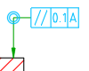
All Around Adds the all around indication to the symbol. This option is unavailable for the GOST standard. |
|||
|
All Over Adds the all over indication to the symbol. This option is available only in ISO 1101:2017(E) revision.
 |
|||
|
Indicator Type Displays the types of plane and feature indicators. |
|||
|
Intersection Plane Indicator
 |
|||
|
Orientation Plane Indicator
 |
|||
|
Collection Plane Indicator
 |
|||
|
Direction Feature Indicator
 |
|||
|
Indicator Geometric Symbol Displays a list of symbols that allows you to specify the geometric characteristic when defining tolerance. |
|||
|
Indicator Datum Specifies the datum for plane and feature indicators. |
|||
|
Add Symbol Adds a new plane and feature indicator symbol. By default, this button is inactive. This button is active only when there is value in the indicator datum. This option is available only in ISO 1101:2017(E) revision. |
|||
|
Delete Symbol Deletes the selected plane and feature indicator symbol. This button is active only when there are two or more symbols. This option is available only in the ISO 1101:2017(E) revision. |
|||
|
Previous Symbol Moves from the current symbol to the previous symbol of the plane and feature indicator. This button is active only when there are two or more symbols, and the currently selected symbol is not the first symbol of the plane and feature indicator symbols attached to the tolerance indicator. This option is available only in the ISO 1101:2017(E) revision. |
|||
|
Next Symbol Moves from the current symbol to the next symbol of the plane and feature indicator. This button is active only when there are two or more symbols, and the currently selected symbol is not the last symbol of the plane and feature indicator symbols attached to the tolerance indicator. This option is available only in the ISO 1101:2017(E) revision. |
|||
|
Library Lists all feature control frame symbols in the symbol library, for the current drafting standard. |
|||
|
Menu Options |
|||
|
Load Loads the settings of the selected symbol to the Feature Control Frame dialog box. This operation overwrites the current settings of the Feature Control Frame dialog box. |
|||
|
Update Overwrites the selected symbol in the library, with the current settings of the Feature Control Frame dialog box. The preview updates to reflect the new settings. The name of the symbol and default status do not change. |
|||
|
Delete Removes the selected symbol from the library. |
|||
|
Rename Makes the symbol name editable. AutoCAD Mechanical toolset validates the name to ensure that the symbol names are unique. |
|||
|
Set default Makes the selected symbol the default symbol of the library. A blue check mark appears next to the symbol to indicate that it is the default symbol. The next time you create a feature control frame symbol, the default symbol loads automatically. |
|||
|
Remove default Removes the default status of the selected symbol. This menu option is available only on the default symbol. When there is no default symbol selected, the settings default to the settings of the feature control frame symbol you created or edited most recently. |
|||
|
Add Saves current settings to the symbol library as a new item in the library. A prompt enables you to name the new item. |
|||
|
Import Imports the feature control frame symbols from the symbol library of another drawing. You can only import symbols of the same standard and revision as the feature control frame symbol you are editing. |
|||
|
Clear Clears all the data and returns the dialog box options to the default values. |
|||
|
Frame Controls |
|||
|
Add Frame
Adds a new tolerance indicator frame to the existing feature control frame symbol. This option is available only in the ISO 1101:2017(E) revision. |
|||
|
Delete Frame
Deletes the selected tolerance indicator frame. This button is active only when there are two or more frames. Any inline and plane and feature indicator symbols attached to this frame are also deleted. This option is available only in the ISO 1101:2017(E) revision. |
|||
|
Previous Frame
Moves from the current frame to the previous frame of the tolerance indicator frame. This button is active only when there are two or more frames, and the currently selected frame is not the first frame of the feature control frame symbol. This option is available only in the ISO 1101:2017(E) revision. |
|||
|
Next Frame
Moves from the current frame to the next frame of the tolerance indicator frame. This button is active only when there are two or more frames, and the currently selected frame is not the last frame of the feature control frame symbol. This option is available only in the ISO 1101:2017(E) revision. |
|||
|
Leader and Text tab |
|||
|
Leader |
|||
|
Primary arrowhead Specifies the type of the primary leader arrowhead. When the arrowhead is set to By Standard, it acquires the arrowhead from the current drafting standard. Thereafter, if you change the arrowhead selected for the current drafting standard (in the Standard Settings dialog box or Feature Control Frame Settings dialog box) the arrowhead for this symbol updates automatically. |
|||
|
Secondary arrowhead Specifies the type of the secondary leader arrowhead. When the arrowhead is set to By Standard, it acquires the arrowhead from the current drafting standard. Thereafter, if you change the arrowhead selected for the current drafting standard (in the Standard Settings dialog box or Feature Control Frame Settings dialog box) the arrowhead for this symbol updates automatically. |
|||
|
Surface arrowhead Specifies the type of arrowhead to use at the end of the surface indication leader. When the arrowhead is set to By Standard, it acquires the arrowhead from the current drafting standard. Thereafter, if you change the arrowhead selected for the current drafting standard (in the Feature Control Frame Settings dialog box) , the arrowhead for this symbol updates automatically. Note:
This option is available only if a surface indication line exists for the symbol you are editing. |
|||
| Edit leader/segments | |||
|
Add Adds a leader, leader segment(s), or leader node(s). |
|||
|
Remove Deletes a leader, or leader segment(s). |
|||
| Edit object attachment | |||
|
Attach Attaches the symbol to a geometry in the drawing. |
|||
|
Detach Detaches the symbol. The symbol becomes a free-standing object. |
|||
|
Surface extension line Controls options for extension lines to the start point of the leader. Extension lines are drawn only if you move the start point of the leader beyond the end of the line or arc it is attached to. The options in this section are available only if extension lines for this symbol exist. |
|||
|
Offset from object Defines the distance between the extension line’s start point and the attached object. |
|||
|
Sync Loads values for the offset from the DIMEXO system variable. 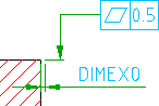
|
|||
|
Extension beyond leader Defines the distance between the leader start point and the extension line end point. |
|||
|
Sync Loads values for the extension from the DIMEXE system variable. 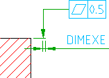
|
|||
|
Settings Opens the Feature Control Frame Settings dialog box, enabling you to edit the default settings for the current drafting standard. |
|||


