3. Create, Open, Save, and View Drawings
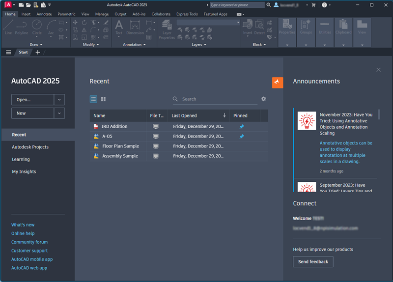
When AutoCAD starts, you'll see the Start tab. This is where you can quickly start a new drawing, open an existing drawing file or template, save it, and then view it.
You can also accomplish all of this through the Quick Access toolbar. We'll show you how.
Learning Objectives
Prerequisites
- AutoCAD 2024 or later has been installed
Prepare for the Exercises
To follow along with the exercises in this topic, download the ZIP file containing the sample drawings.
![]() Download: Sample drawing files used for the following exercises
Download: Sample drawing files used for the following exercises
The ZIP file contains all drawings used for the exercises and only needs to be downloaded once. Keep the ZIP file to restore the original state of the sample drawings.
Navigate the Start tab
The Start tab provides easy access to create, open, save, and view drawings.
On the Start tab, click the Open drop-down to see the options.
- Open files - Open a previously saved drawing file.
- Open a sheet set - Open a previously saved sheet set.
- Explore sample drawings - Access the installed sample files.
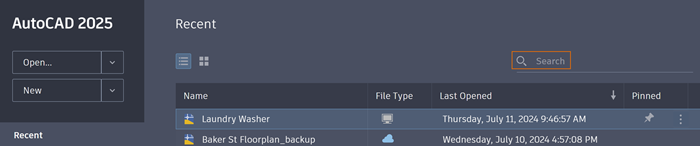
On the left side, click Recent. Here, you can view recently opened drawings.
Below, click Learning to see learning resources such as videos and tips.
Click My Insights to see content recommendations personalized to you. As a new AutoCAD user, you may not yet have any insights available to you. After you've used AutoCAD for about a month, this area will show insights and suggestions based on your activity.
Create a New Drawing
There are two easy ways to create a new drawing:
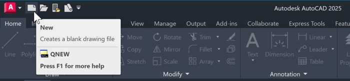
- On the Start tab, click New.
- Or, on the Quick Access toolbar, click New
 , which will give you drawing template options to get started. A drawing template file contains predefined settings, standards, and definitions that will save you significant setup time.
Try It: Use a Drawing Template
In this exercise, open and select a drawing template.
On the Quick Access toolbar, click New.
In the Select template dialog box, select one of the following drawing template files based your associated industry and click Open.
- Tutorial-mArch.dwt. Sample architectural template (metric)
- Tutorial-mMfg.dwt. Sample mechanical design template (metric)
- Tutorial-iArch.dwt. Sample architectural template (imperial)
- Tutorial-iMfg.dwt. Sample mechanical design template (imperial)
The metric template files are scaled to use millimeters as the drawing unit, and the imperial template files are scaled to use inches as the drawing unit.
Set the Units of a Drawing
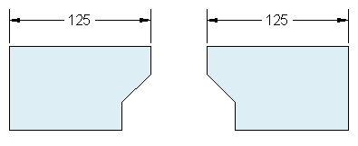
After you start a new drawing, you'll first decide what the length of one unit represents—an inch, a foot, a centimeter, a kilometer, or some other unit of length. For example, the objects below could represent two buildings that are each 125 feet long, or they could represent a section from a mechanical part that is measured in millimeters.
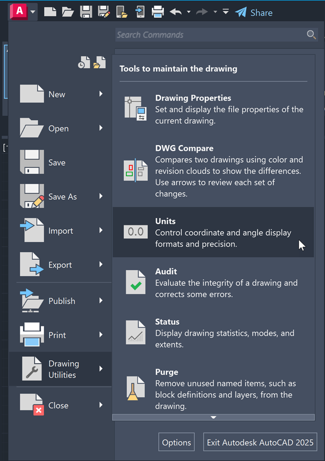
Click on Application menu > Drawing Utilities > Units to open the Drawing Units dialog box.
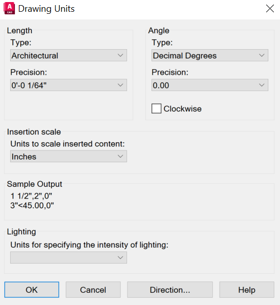
Under Length, select a Type, depending on what format you'd like for your drawing units. For example, if you are a mechanical engineer who normally works in millimeters, set the format for linear units to decimal. If you are an architect who normally works in feet and inches, set the format to architectural. The format settings available for linear units are as follows:
- Architectural. A length of 15.5 units displays as 1’-3 1/2”
- Decimal. A length of 15.5 units displays as 15.5000
- Engineering. A length of 15.5 units displays as 1’-3.5”
- Fractional. A length of 15.5 units displays as 15 1/2
- Scientific. A length of 15.5 units displays as 1.5000E+1
Make a selection under Precision to set the decimal or fractional rounding of values displayed on-screen.
Under Angle, select an angle type, precision, and direction for positive rotation for angular drawing units.
Click OK to save the settings.
Understand and Switch Between Model and Layout Tabs
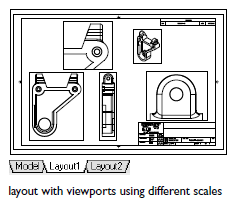
The Model and Layout tabs provide two working environments. In Model space, you can draw a full-size model of your object. With Layout space, you can create a layout of the same object from multiple angles.
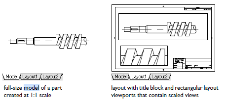
Model space accesses a limitless drawing area. In model space, you first decide whether one unit represents one millimeter, one meter, one inch, or some other drawing unit. Next, you set the drawing unit format. Then you draw at 1:1 scale.
Layout space accesses drawing layouts. When you set up a layout, you specify the paper size you want to use. The layout represents a printed drawing sheet in which you can display one or more views of the model at various scales. This layout environment is called paper space. Here you create layout viewports that act as windows into model space. Each layout viewport can contain a different view of the model.
Try It: Switch between Model and Layout Spaces
In this exercise, navigate between model and layout spaces.
At the bottom left of your window, see the Model tab. This shows that your drawing is currently in Model space, where you create and modify the geometry for your model.
Click the Layout tab to the right of the Model tab. Layouts are used to generate printed drawings.
On the layout, double-click anywhere within the rectangular viewport. This creates Model space within the layout to pan the model space view and add dimensions. To check this, see the bottom right of your window where it should say MODEL.
Double-click in a blank area outside the rectangular viewport. This returns you to Paper space, which you can verify at the bottom right of your window.
To return to Model space, click the Model tab.
Save the Current Drawing
Now that you've created and set the units of a drawing, here are two ways to save it from the Quick Access toolbar:
- Click Save.Find
- Click Save As... to save a copy of the drawing file under a new filename.Find
Try It: Save a Drawing
In this exercise, save your drawing.
- Click Save.Find
In the Save In drop-down list, select a location, such as Documents.
Enter a file name.
Click Save.
To save all open drawings, right-click one of the tabs at the top of the window and click Save All.
Close an Open Drawing
To close your drawing, click the X on the File tab.
You can also right-click a file tab and click Close All.
Open an Existing Drawing
Here's how to open existing drawings.
To Open a Drawing Using the Filename
Or search for the file by name on the Recent tab in the Search bar.
To Open a Recently Opened File
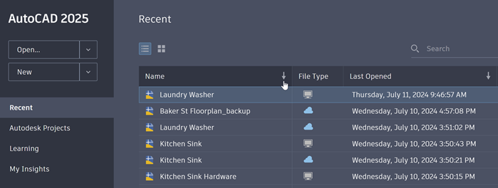
From the Start tab page, click Recent on the left-hand side to open a recently opened file. For more precise navigation, sort files by Name or Last Opened by clicking on the column headers, available only in list view.
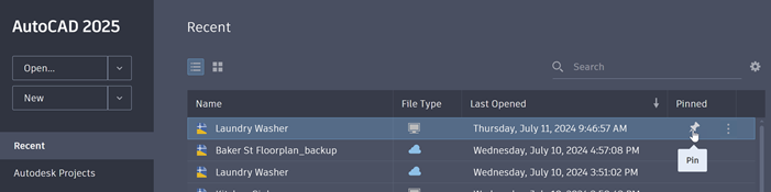
To Pin a Drawing
Pinned drawings will appear at the top of the Recent file list for easy access. From the Start tab page, click Recent, then the thumbtack to pin.
View and Navigate Drawings
The easiest way to change the view of and navigate your drawing is to use the wheel on your mouse.
- Pan a view in any direction by holding the wheel down and then moving your mouse.
- Zoom in or out by rolling the wheel.
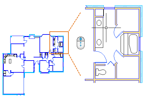
When you zoom in or out, the location of the cursor is important. Think of your cursor as a magnifying glass. For example, if you position the cursor in the upper-right area of the floor plan as shown below, rolling the mouse wheel magnifies that area without shifting it.
Try It: Zoom and Pan with the Navigation Bar
In this exercise, use the Navigation Bar to zoom and pan.
Using the Navigation Bar:
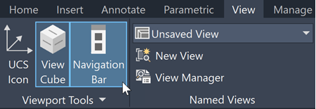
In the View tab and check that Navigation Bar is in blue. If not, click Navigation Bar to turn it on.
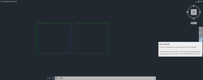
- On the Navigation Bar, click the Zoom drop-down menu and choose Zoom Extents.Find
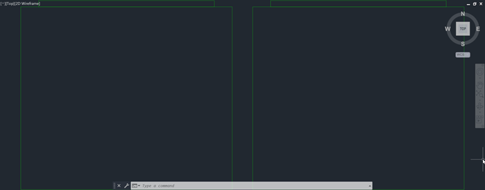
The drawing zooms out to its extents.
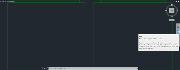
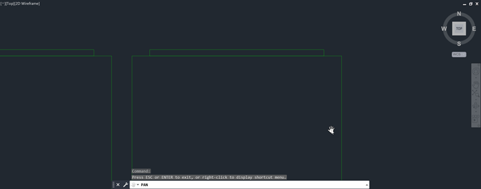
- On the Navigation Bar, click Pan.Find
Click and drag to move the view to a specific area of the drawing.
Using the Mouse:
- To see Zoom Extents, double-click the scroll wheel.
- To zoom to a specific location, put the cursor at the spot and scroll up to zoom in. Scroll downwards to zoom out.
- To pan, hold the scroll wheel and drag to where you want to zoom.
Summary
In this lesson, you learned to navigate the Start tab and the basics of managing drawing files. This included creating a new drawing from a default drawing template, saving the drawing you created, and then opening that drawing from the recent drawing list. For more information on the Start tab and drawing file management, see the Related sections below.
Related Commands
| Command | Description |
|---|---|
| CLOSE | Creates and modifies drawing layouts. |
| CLOSEALL | Closes all currently open drawings. |
| NAVBAR | Provides access to viewing tools from a unified interface. |
| NEW | Creates a new drawing. |
| OPEN | Opens an existing drawing file. |
| PAN | Shifts the view without changing the viewing direction or magnification. |
| SAVE | Saves the current drawing under a different file name or location without changing which drawing file is the current one. |
| SAVEAS | Saves a copy of the current drawing under a new file name or location. |
| UNITS | Controls the precision and display formats for coordinates, distances, and angles. |
| ZOOM | Increases or decreases the magnification of the view in the current viewport. |