2B. Mechanical Design: Square Flange Plate
In this exercise, you will create a top and side section view of a square flange plate.
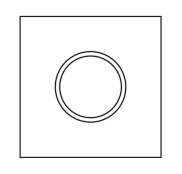
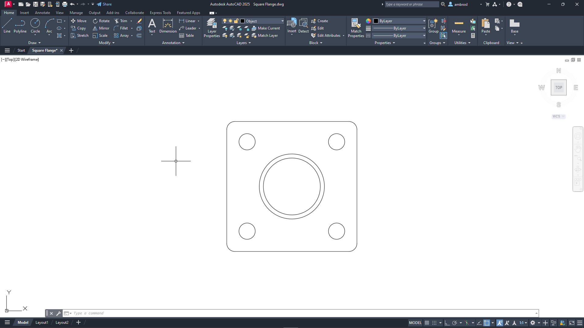
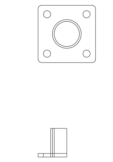
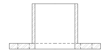
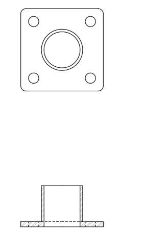
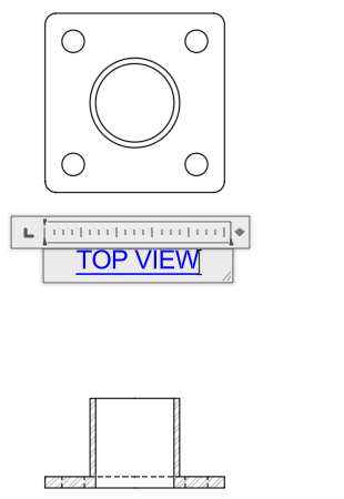
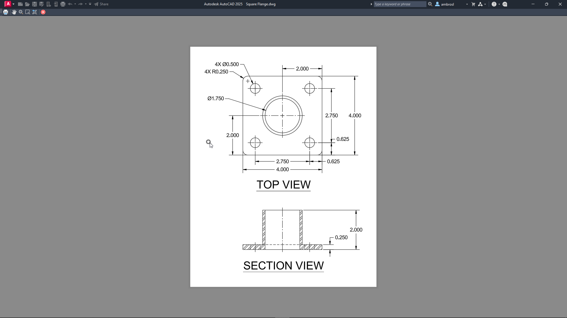
After you complete all the exercises, you should have a drawing that looks similar to the following image.
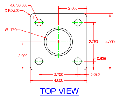
The completed drawing can be found in the Squared Flange - Complete.dwg file.
Learning Objectives
- Create a new drawing file
- Create new layers
- Create objects that define the top and side views of the square flange
- Use construction lines to project features from the top to side view
- Duplicate objects by offsetting, arraying, mirroring, and copying
- Trim and erase objects
- Breaking and joining objects
- Apply hatches to closed objects
- Add and edit annotation
- Add center marks and dimensions
- Plot the design to a PDF file
Prerequisites
AutoCAD 2024 or later has been installed
Don't currently have AutoCAD installed? You can download AutoCAD from your Autodesk Account or a trial from Autodesk.com.
Prepare for the Exercises
To follow along with the exercises in this topic, download the ZIP file containing the sample drawings.
![]() Download: Sample drawing files used for the following exercises
Download: Sample drawing files used for the following exercises
The ZIP file contains all drawings used for the exercises and only needs to be downloaded once. Keep the ZIP file to restore the original state of the sample drawings.
Before Starting
Here are a few things you should know before getting started:
- Values to be entered or typed in response to a command or dialog box value are presented in bold.
- Pressing the Esc key ends the current command. Once the current command is ended, you can start the command over or undo a recent change.
- Clicking Undo on the Quick Access toolbar reverses the effect of recently used commands.Find
Exercise 1: Create a new drawing from a template file
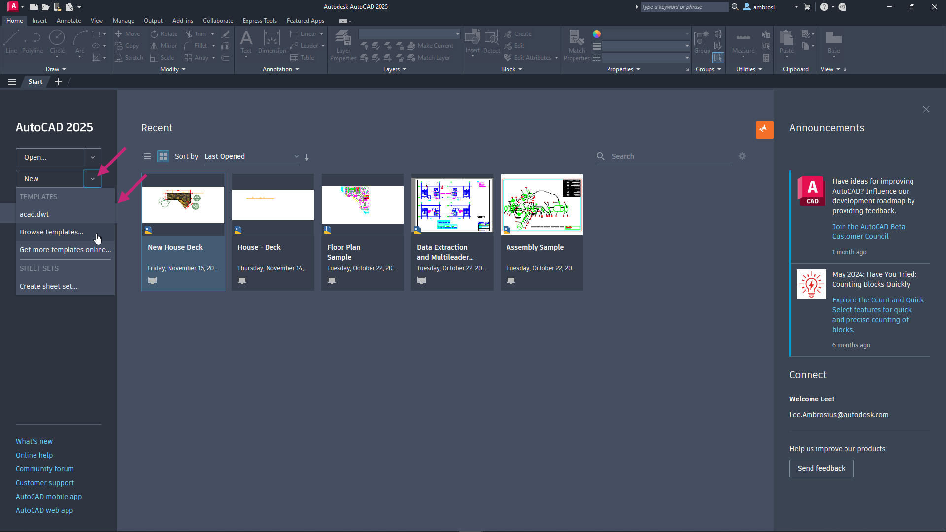
Create and save a new drawing based on a template file.On the Start tab, click the New drop-down menu and choose Browse Templates.
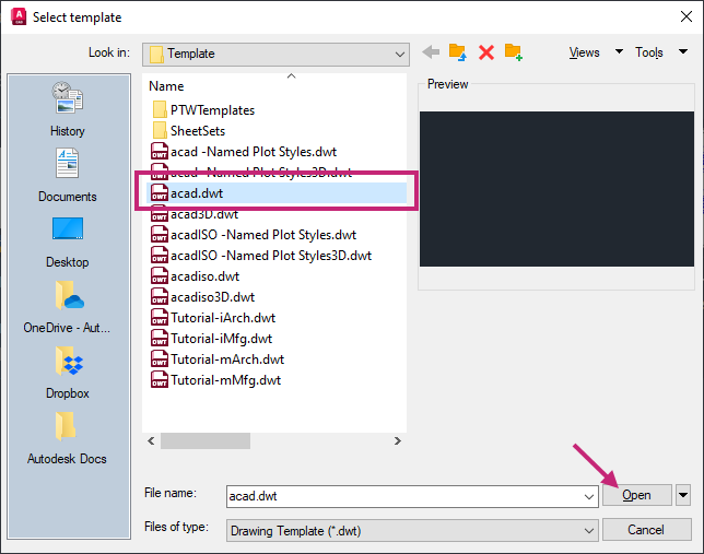
In the Select Template dialog box, select acad.dwt from the Files list and click Open.
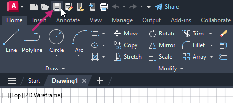
- On the Quick Access toolbar, click Save.Find
In the Save Drawing As dialog box, browse to the Documents folder.
In the File Name text box, select the current name and Square Flange. Click Save.
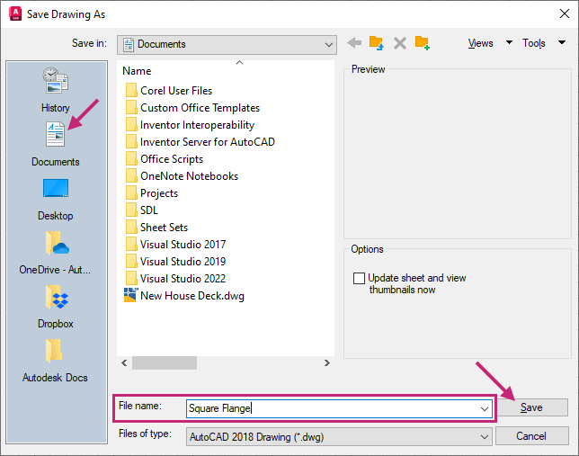
A new drawing file is created and named Square Flange in the Documents folder. Make sure you continue with this file for the remainder of the exercises.
Exercise 2: Load linetypes
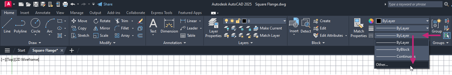
Load linetypes that can be assigned to individual objects or layers.- On the ribbon, click Home tab > Properties panel > Linetypes drop-down list > Other.Find
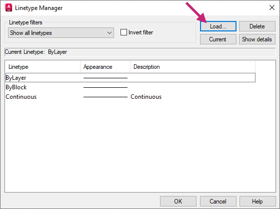
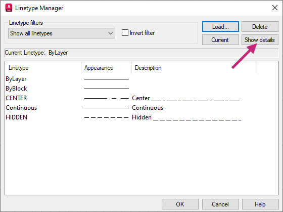
In the Linetype Manager dialog box, click Load.
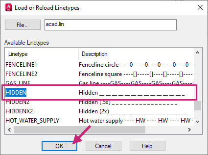
In the Load or Reload Linetypes dialog box, hold down the Ctrl key and select CENTER and HIDDEN in the list of linetypes. Click OK.
In the Linetype Manager dialog box, click Show Details.
Under Details, in the Global Scale Factor text box, replace the current value with 0.5.
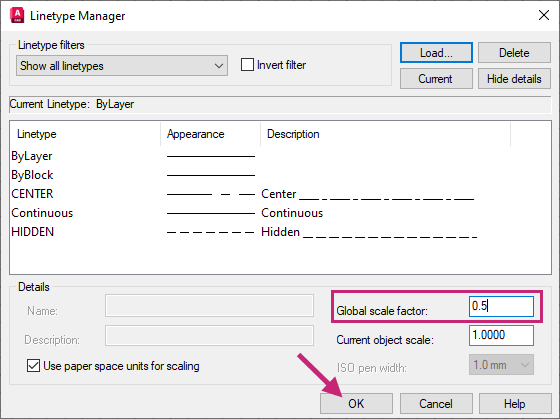
In the Linetype Manager dialog box, click OK.
- On the Quick Access toolbar, click Save.Find
Exercise 3: Create new layers
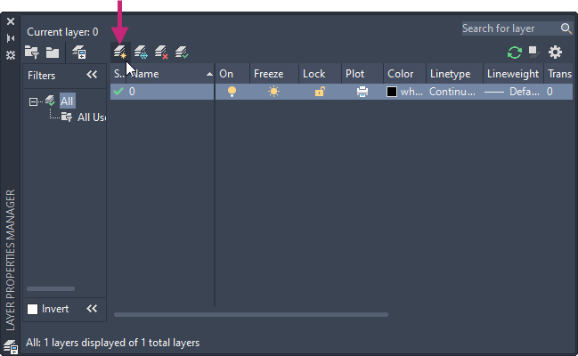
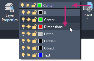
Create new layers that will be used to organize objects in the drawing.- On the ribbon, click Home tab > Layers panel > Layer Properties.Find
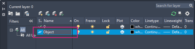
On the Layer Properties Manager palette, click New Layer.
In the in-place editor, enter Object.
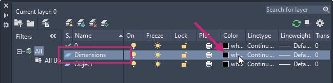
Create a second layer and name it Dimensions.
On the Dimensions row, under the Color column, click the color swatch.
In the Select Color dialog box, Index Color tab, click the Red (1) color swatch and then click OK.
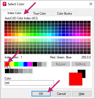 Note:
Note:Colors 1 through 9 can all be found in the same row in the Color dialog box.
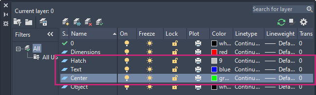
Create a third layer with the name Hatch and assign it the 9 color.
Create a fourth layer with the name Text and assign it the Blue (5) color.
Create a fifth layer with the name Center and assign it the Green (3) color.
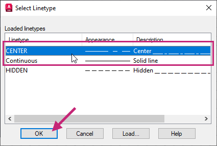
On the Center row, under the Linetype column, click Continuous.
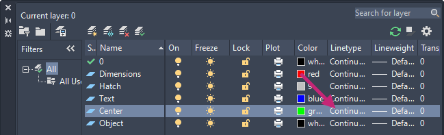
In the Select Linetype dialog box, select CENTER and then click OK.
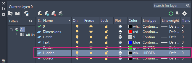
Create a sixth and final layer with the name Hidden and assign it the White (7) color and HIDDEN linetype.
 Tip:
Tip:When creating a new layer, select a layer with properties similar to the ones you want for the new layer. The new layer will inherit the properties of the selected layer.
- On the ribbon, click Home tab > Layers panel > Layer Properties to close the Layer Properties Manager.Find
You can also click the Close button the title bar of the Layer Properties Manager.
- On the Quick Access toolbar, click Save.Find
Exercise 4: Define the top view of the square flange
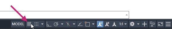
Create straight and curved objects that create the top view of the square flange.- On the status bar, click the Grid Drawing Display button.Find
The button should now no longer be highlighted and the grid in the drawing area is removed.
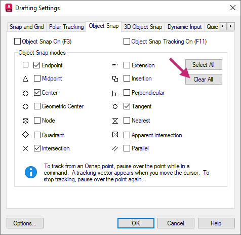
- On the status bar, right-click over the Snap Cursor to 2D Reference Points button and choose Object Snap Settings.Find
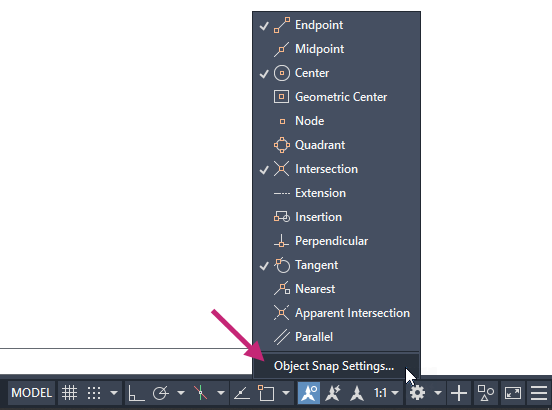
In the Drafting Settings dialog box, Object Snap tab, click Clear All.
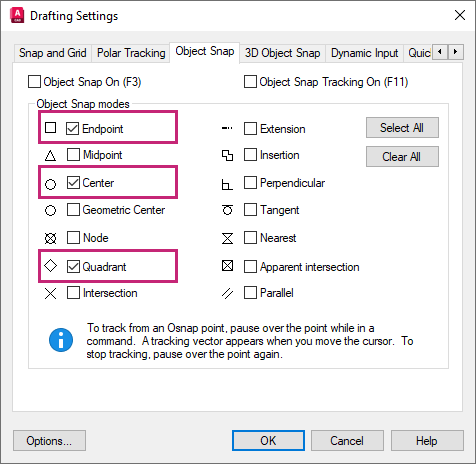
Under the Object Snap Modes section, click Endpoint, Center and Quadrant.
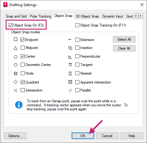
Click Object Snap On, if it is currently unchecked, and then click OK.
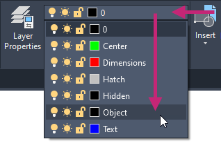
On the ribbon, click Home tab > Layers panel > Layers drop-down list and choose Object.
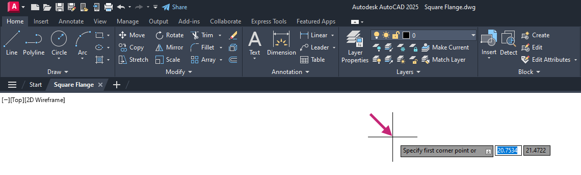
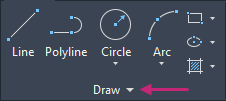
- Click Home tab > Draw panel > Rectangle\Polygon drop-down menu > Rectangle.Find
At the Specify first corner point or [Chamfer/Elevation/Fillet/Thickness/Width]: prompt, click near the center of the drawing area.
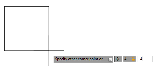
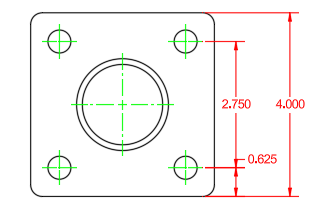
At the Specify other corner point or [Area/Dimensions/Rotation]: prompt, enter @4,-4.
A rectangle that is 4x4 units is created.
- Click Home tab > Draw panel > Circle drop-down menu > Center, Radius.Find
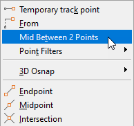
At the Specify center point for circle or [3P/2P/Ttr (tan tan radius)]: prompt, hold down the Shift key and right-click.
From the Object Snap menu, choose Mid Between 2 Points.
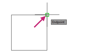
At the First point of mid: prompt, move the cursor to the endpoint of the lower-left corner of the rectangle and click when the Endpoint object snap marker and tooltip appear.
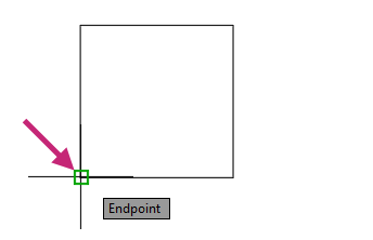
At the Second point of mid: prompt, move the cursor to the endpoint of the upper-right corner of the rectangle and click when the Endpoint object snap marker and tooltip appear.
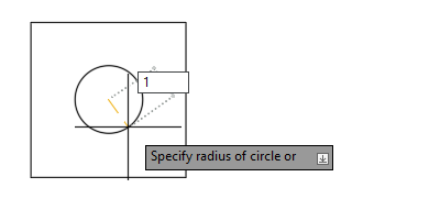
At the Specify radius of circle or [Diameter]: prompt, enter 1.
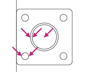
- Click Home tab > Modify panel > Offset.Find
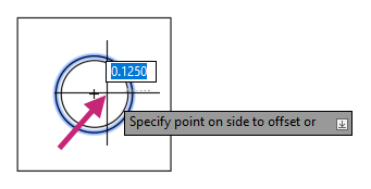
At the Specify offset distance or [Through/Erase/Layer] <Through>: prompt, enter 0.125.
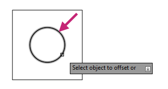
At the Select object to offset or [Exit/Undo] <Exit>: prompt, select the circle in the center of the rectangle.
At the Specify point on side to offset or [Exit/Multiple/Undo] <Exit>: prompt, specify a point inside of the circle to offset the circle inward.
At the Select object to offset or [Exit/Undo] <Exit>: prompt, press Enter to exit the command.
Press Enter again to repeat the OFFSET command.
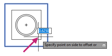
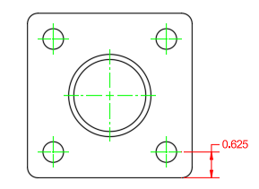
At the Specify offset distance or [Through/Erase/Layer] <Through>: prompt, enter 0.625.
At the Select object to offset or [Exit/Undo] <Exit>: prompt, select the rectangle.
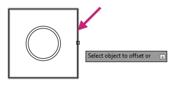
At the Specify point on side to offset or [Exit/Multiple/Undo] <Exit>: prompt, specify a point inside of the rectangle to offset the rectangle inward.
At the Select object to offset or [Exit/Undo] <Exit>: prompt, press Enter to exit the command.
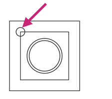
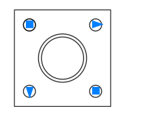
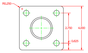
Draw a circle with a radius of 0.25 at the upper-left corner of the innermost rectangle.
- Click Home tab > Modify panel > Erase.Find
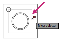
At the Select objects: prompt, select the innermost rectangle and press Enter.
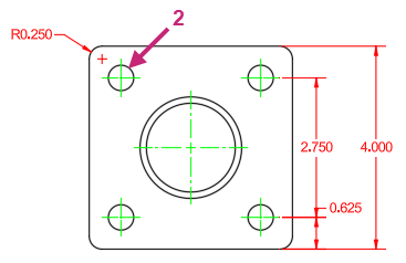
- Click Home tab > Modify panel > Array drop-down menu > Rectangular Array.Find
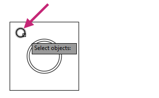
At the Select objects: prompt, select the small circle recently added and press Enter.
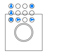
On the Array Creation contextual tab, do the following:
On the Columns panel, change Columns to 2 and Between to 2.75.
On the Rows panel, change Rows to 2 and Between to -2.75.
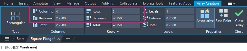
- On the Close panel, click Close Array.Find
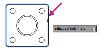
- Click Home tab > Modify panel > Fillet\Chamfer drop-down menu > Fillet.Find
At the Select first object or [Undo/Polyline/Radius/Trim/Multiple]: prompt, enter r.
At the Specify fillet radius <0.0000>: prompt, enter 0.25.
At the Select first object or [Undo/Polyline/Radius/Trim/Multiple]: prompt, enter p.
At the Select 2D polyline or [Radius]: prompt, select the rectangle.
- On the Quick Access toolbar, click Save.Find
Exercise 5: Navigate the drawing
Use the Zoom and Pan tools on the Navigation Bar, which you'll continue to use in the following exercises.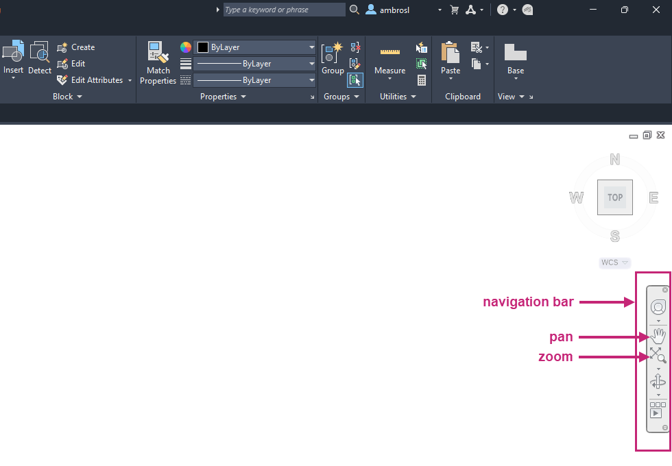
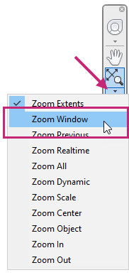
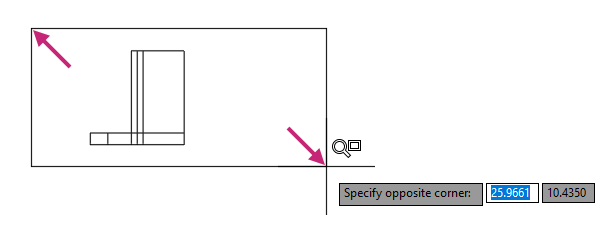
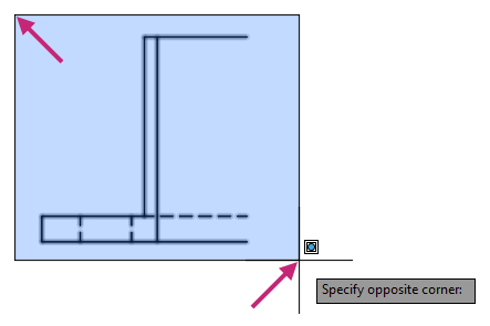
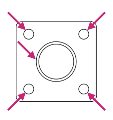
- On the Navigation Bar, click Zoom drop-down menu > Zoom Window.Find
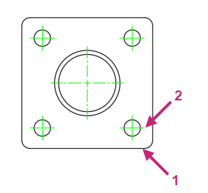
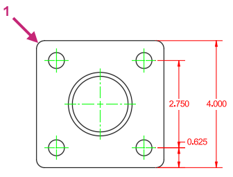
At the Specify first corner: prompt, in the drawing area, click a point near (1) in the following image.
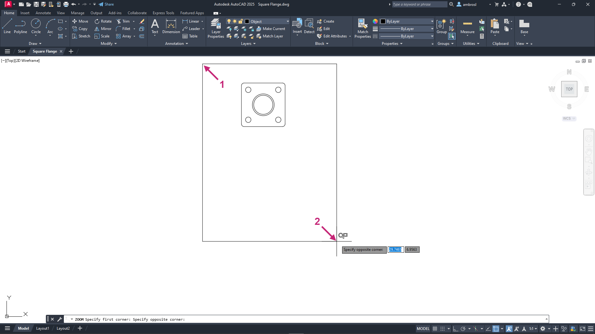
At the Specify opposite corner: prompt, in the drawing area, click a point near (2) in the previous image.
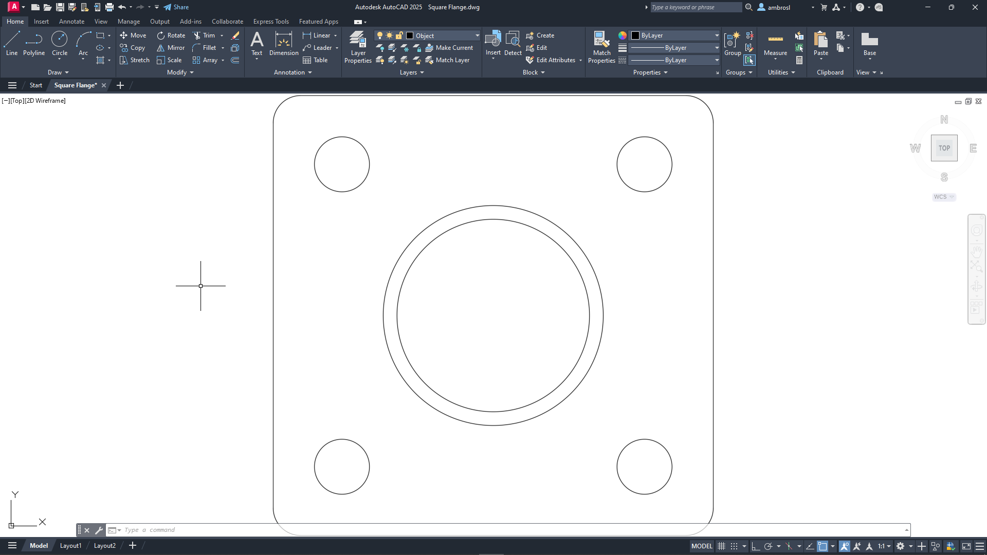
The objects within the window are enlarged and centered in the drawing area.
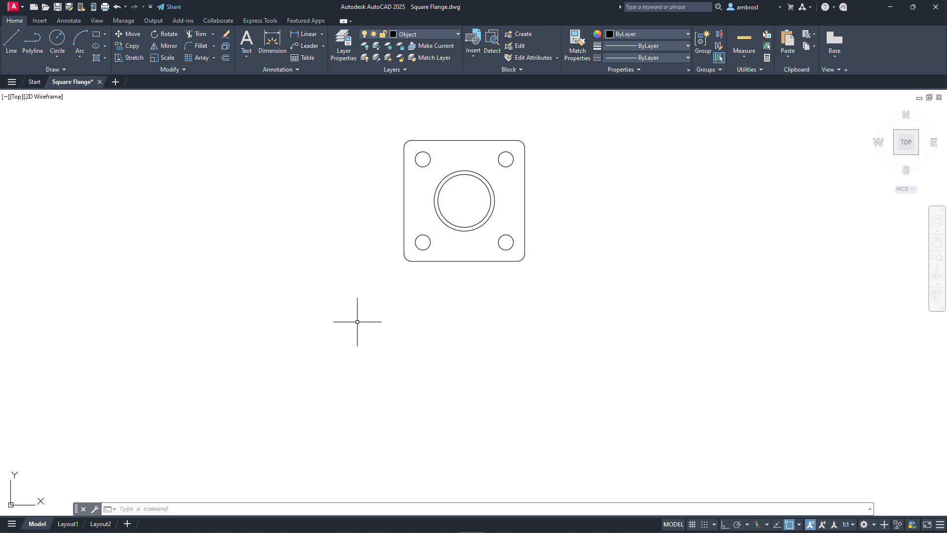
- On the Navigation Bar, click Zoom drop-down menu > Zoom Extents.Find
The extents of all objects should now fill the entire drawing window.
- On the Navigation Bar, click Zoom drop-down menu > Zoom Out.Find
The objects should now appear smaller and provide some additional space to work.
Zoom out again by repeating the previous step.
- On the Navigation Bar, click Pan.Find
In the drawing area, click and hold the left mouse button.
While holding the left mouse button down, drag the cursor upward and release once the top-most horizontal line is near the top of the drawing area.
The square flange should move upward towards the top of the screen.
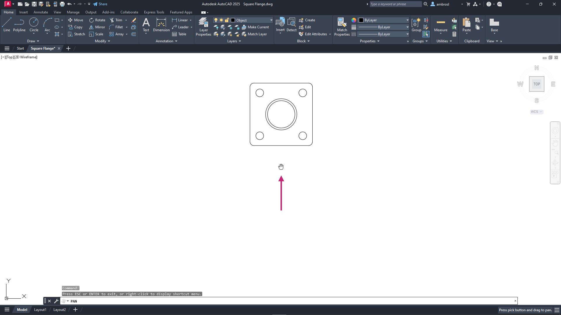
Press the Esc key to exit the PAN command.
- On the Quick Access toolbar, click Save.Find
When using a mouse you can hold down the mouse wheel to pan the drawing, double-click the mouse wheel to zoom to the extents of the drawing, and scroll the mouse wheel to zoom in and out. If you're using a touchpad, you can drag two fingers to zoom in and out.
Exercise 6: Define the side view of the square flange
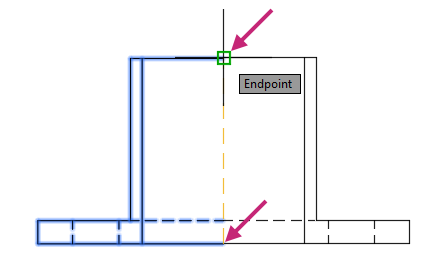
Create construction lines to assist in the creation of the side view of the square flange.- On the ribbon, click Home tab > Draw panel (expanded) > Construction Line.Find
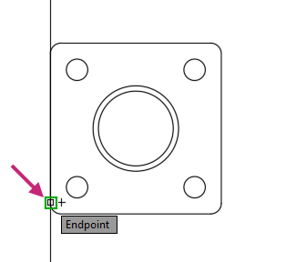
At the Specify a point or [Hor/Ver/Ang/Bisect/Offset]: prompt, enter v.
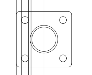
At the Specify through point: prompt, move the cursor to the bottom endpoint of the vertical line on the left side and click when the Endpoint object snap marker and tooltip appear.
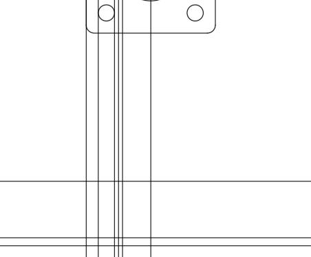
Continue specifying points based on the following image.
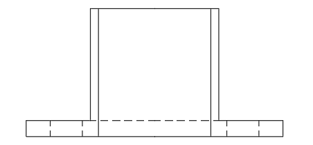
Your drawing should now look like the following image.
At the Select object to offset or [Exit/Undo] <Exit>: prompt, press Enter to end the XLINE command.
Press Enter again to repeat the XLINE command.
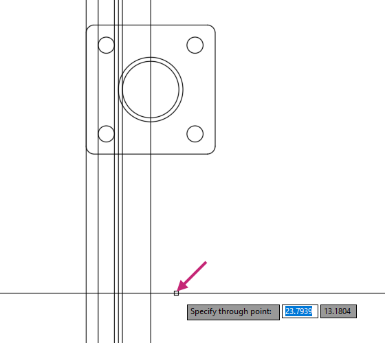
At the Specify a point or [Hor/Ver/Ang/Bisect/Offset]: prompt, enter h.
At the Specify through point: prompt, move the cursor below the rectangle of the top view and click to specify a point. Press Enter to end the XLINE command.
An exact point isn't necessary, as you can always move the objects later to increase the distance if needed.
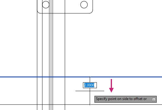
- Click Home tab > Modify panel > Offset.Find
At the Specify offset distance or [Through/Erase/Layer] <Through>: prompt, enter 2.
At the Select object to offset or [Exit/Undo] <Exit>: prompt, select the recently created horizontal construction line.
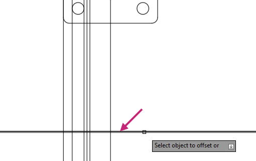
At the Specify point on side to offset or [Exit/Multiple/Undo] <Exit>: prompt, specify a point below the horizontal construction line and press Enter to exit the command.
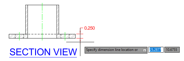
Repeat the OFFSET command and offset the bottom horizontal construction line up 0.25.
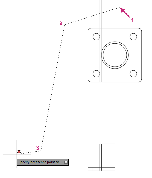
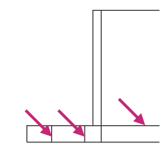
- Click Home tab > Modify panel > Trim/Extend drop-down menu > Trim.Find
At the Select object to trim or shift-select to extend or [cuTting edges/Crossing/mOde/Project/eRase]: prompt, enter f.
At the Specify first fence point or pick/drag cursor: prompt, specify a point located near (1) in the following image.
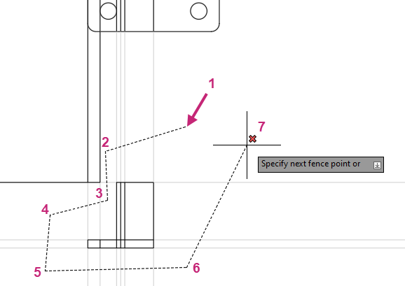
At the Specify next fence point or [Undo]: prompt, continue specifying points as indicated in the previous image.
Press Enter twice to trim the construction lines and end the TRIM command.
- Click Home tab > Modify panel > Erase.Find
At the Select objects: prompt, enter f.
At the Specify first fence point or pick/drag cursor: prompt, specify the points as indicated in the following image.
Press Enter twice to erase the selected construction lines and end the ERASE command.
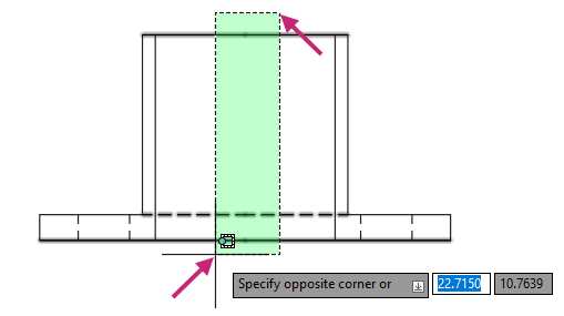
- On the Navigation Bar, click Zoom drop-down menu > Zoom Windowand specify two points around the objects that currently make up the side view.Find
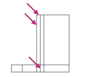
- On the ribbon, click Home tab > Modify panel > Trim/Extend drop-down menu > Trim.Find
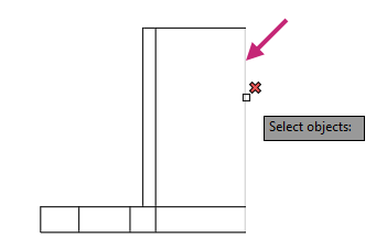
At the Select object to trim or shift-select to extend or [cuTting edges/Crossing/mOde/Project/eRase]: prompt, select the objects at the points shown in the following image and press Enter to end the TRIM command.
- Click Home tab > Modify panel > Erase.Find
At the Select objects: prompt, select the right-most line and press Enter to end the ERASE command.
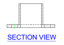
- Click Home tab > Modify panel (expanded) > Break at Point.Find
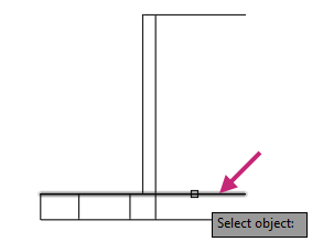
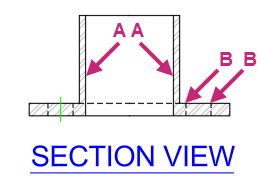
At the Select objects: prompt, select the line as indicated in the following image.
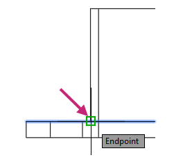
At the Specify break point: prompt, specify the endpoint as indicated in the following image.
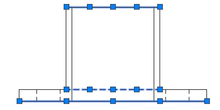
Press Esc to make sure no command is active and then select the lines indicated in the following image.
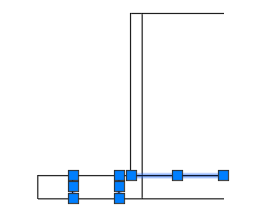
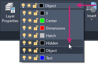
Click Home tab > Layers panel > Layers drop-down list and choose Hidden.
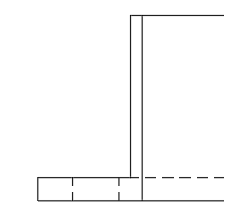
Press Esc to deselect the selected lines.
- Click Home tab > Modify panel > Mirror.Find
At the prompt, specify two points around the objects that currently make up the side view and press Enter to end object selection.
At the Specify first point of mirror line: prompt, specify the right endpoint of the bottom line.
At the Specify second point of mirror line: prompt, specify the right endpoint of the top line.
At the Erase source objects? [Yes/No] <No>: prompt, press Enter to keep the original selected objects.
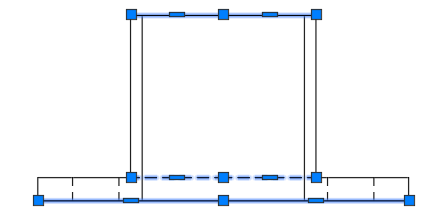
With no command current, select the two top, two middle, and two bottom lines.
- Click Home tab > Modify panel (expanded) > Join.Find
The six selected lines are joined into three polylines.
- On the Quick Access toolbar, click Save.Find
Exercise 7: Apply hatches and fills
Apply hatch patterns and fills to enhance the visualization of the deck.Press Esc to make sure no objects are selected.
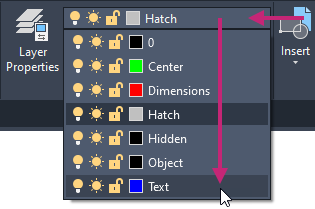
On the ribbon, click Home tab > Layers panel > Layers drop-down list and choose Hatch.
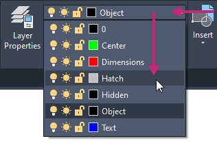
- Click Home tab > Draw panel > Hatch drop-down menu > Hatch.Find
Click Hatch Creation contextual tab > Pattern panel > Pattern gallery > ANSI32.
From the Hatch Creation contextual tab > Properties panel, click in the Hatch Pattern Scale text box, type 0.5, and press Enter.

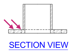
At the Pick internal point or [Select objects/Undo/seTtings]: prompt, specify points within the closed areas as indicated in the following image.
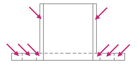
Press Enter to end the HATCH command.
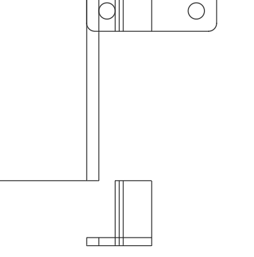
The drawing should now look similar to the following image.
- On the Quick Access toolbar, click Save.Find
Exercise 8: Add annotation labels
Add annotation to label the two views of the square flange.- On the Navigation Bar, click Zoom drop-down menu > Zoom Extents.Find
- On the Navigation Bar, click Zoom drop-down menu > Zoom Out.Find
You should now be able to see both the top and side view of the square flange in the drawing.
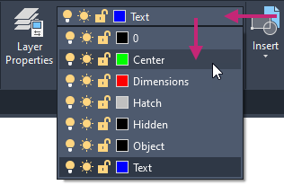
On the ribbon, click Home tab > Layers panel > Layers drop-down list and choose Text.
- Click Annotate tab > Text panel > Text drop-down menu > Multiline Text.Find
At the Specify first corner: prompt, specify a point below and to the left of the objects that make up the top view.
Save some space below the objects of the top view for dimensions later, you can always move the text or objects later as needed.
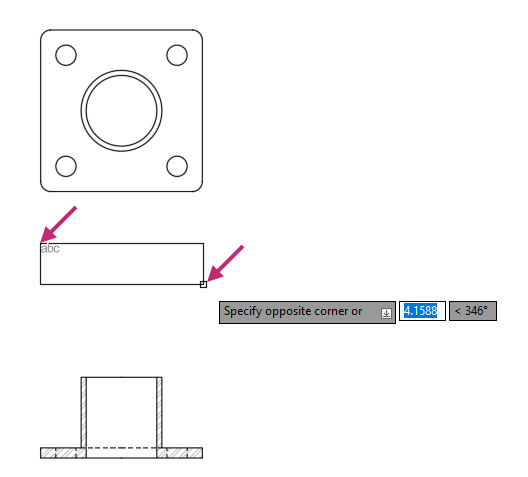
At the Specify opposite corner or [Height/Justify/Line spacing/Rotation/Style/Width/Columns]: prompt, specify a point below and to the right of the top view objects.
On the Text Editor contextual tab, do the following:
On the Style panel, change the Text Height to 0.4 and press Enter to commit the change.
On the Formatting panel, click Underline.
On the Paragraph panel, click Justification drop-down menu > Top Center TC.
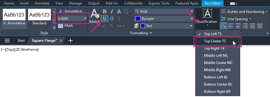
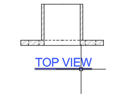
In the in-place text editor, type TOP VIEW.
- Click Text Editor contextual tab > Close panel > Close Text Editor.
- Click Home tab > Modify panel > Copy.Find
At the Select objects: prompt, select the multiline text (mtext) object that was just created and press Enter.
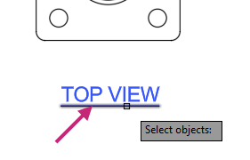
At the Specify base point or [Displacement/mOde] <Displacement>: prompt, specify any point near the mtext object.
At the Specify second point or [Array] <use first point as displacement>: prompt, enter <90 or click Restrict Cursor Orthogonally on the status bar to turn it on.
Tip:You can also press F8 to toggle the status of Restrict Cursor Orthogonally.
At the Specify second point or [Array] <use first point as displacement>: prompt, move the cursor below the objects that make up the side view and specify the point at which the mtext object should be copied.
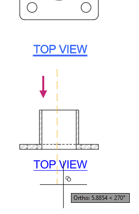
Press Enter to exit the COPY command.
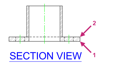
Move the cursor over the copied mtext object and when highlighted, double-click.
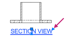
In the in-place editor, change the text string to SECTION VIEW and click outside of the in-place editor to commit the changes.
If the text string SECTION VIEW is on two lines, select the mtext object and click the right-most triangle grip. Drag to the right and click to resize the mtext.
- On the Quick Access toolbar, click Save.Find
Exercise 9: Add center marks and center lines
Add center marks and centerlines to improve the communication of dimensions that will be added in the next exercise.- On the Navigation Bar, click Zoom drop-down menu > Zoom Extents.Find
The extents of all objects should now fill the entire drawing window.
Press Esc to make sure no objects are selected.
On the ribbon, click Home tab > Layers panel > Layers drop-down list and choose Center.
- Click Annotate tab > Centerlines panel > Center Mark.Find
At the Select circle or arc to add center mark: prompt, select the 4 small circles and the outermost circle in the center of the top view.
Press Enter to end the CENTERMARK command.
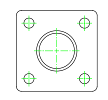
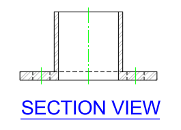
- Click Annotate tab > Centerlines panel > Centerline.Find
At the Select first line: prompt, select one of the lines indicated in the following image.
At the Select second line: prompt, select the other line indicated in the previous image.
Press Enter to repeat the CENTERLINE command and select the line pairings indicated in the following image.
- On the Quick Access toolbar, click Save.Find
Exercise 10: Add basic dimensions
Add dimensions to communicate the overall dimensions of the square flange.On the ribbon, click Home tab > Layers panel > Layers drop-down list and choose Dimensions.
- On the Navigation Bar, click Zoom drop-down menu > Zoom Window and then specify a window around the side view.Find
On the ribbon, click Annotate tab > Dimensions panel > Dimension Styles drop-down list and choose Manage Dimension Styles.
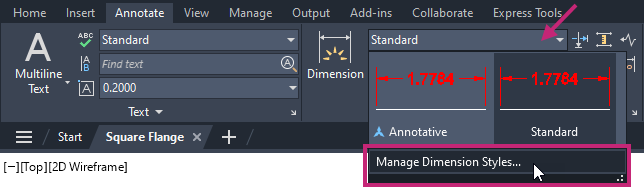
In the Dimension Style Manager dialog box, under Styles, select Standard from the list and click Set Current.
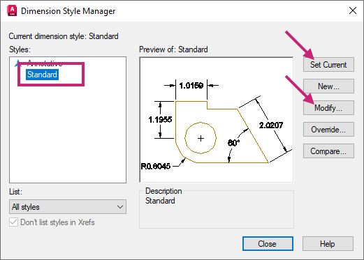
Click Modify.
In the Modify Dimension Style: Standard dialog box, Primary Units tab, click the Precision drop-down list and choose 0.000.
Dimensions will now be displayed with a precision of three digits after the decimal rather than four.
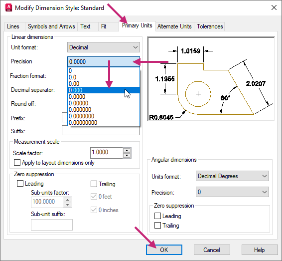
Click OK to exit the dialog box.
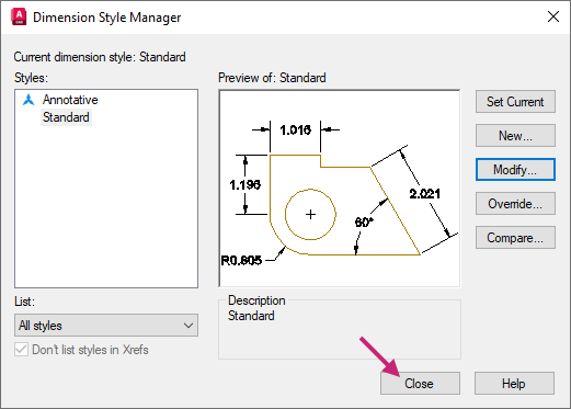
In the Dimension Style Manager dialog box, click Close to exit the dialog box.
- On the ribbon, click Annotate tab > Dimensions panel > Dimensions drop-down menu > Linear.Find
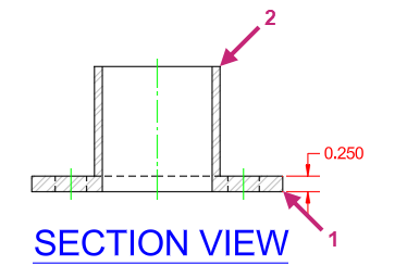
At the Specify first extension line origin or <select object>: prompt, specify the endpoint indicated at (1).
At the Specify second extension line origin: prompt, specify the endpoint indicated at (2) in the previous image.
At the Specify dimension line location or [Mtext/Text/Angle/Horizontal/Vertical/Rotated]: prompt, specify a point to the right to place the dimension.
Press Enter to repeat the DIMLINEAR command.
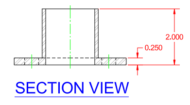
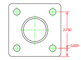
Place the dimension based on the endpoints indicated by (1) and (2) in the following image, and then place the dimension to the right of the previous dimension.
The new vertical dimensions should look similar to the ones in the following image.
Zoom and pan to the objects which define the top view of the square flange.
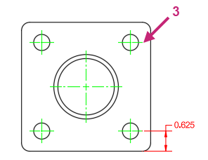
Place a linear dimension based on the endpoints indicated by (1) and (2) in the following image and then place the dimension to the right of the vertical line.
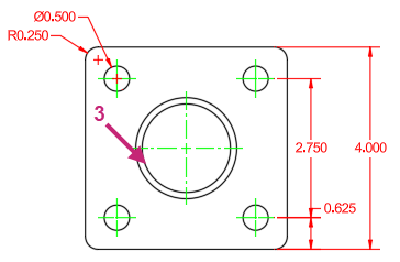
- Click Annotate tab > Dimensions panel > Continue/Baseline drop-down menu > Continue.Find
At the Specify second extension line origin or [Select/Undo] <Select>: prompt, specify the endpoint indicated at (3) in the following image.
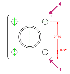
Press Enter twice to end the DIMCONTINUE command.
Place a linear dimension based on the endpoints indicated by (1) and (4) in the following image and then place the dimension to the right of the previous dimensions.
- Click Annotate tab > Dimensions panel > Dimensions drop-down menu > Radius.Find
At the Select arc or circle: prompt, select the fillet indicated at (1).
At the Specify dimension line location or [Mtext/Text/Angle]: prompt, specify a point to the left to place the radial dimension.
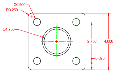
- Click Annotate tab > Dimensions panel > Dimensions drop-down menu > Diameter.Find
At the Select arc or circle: prompt, select the circle indicated at (2) in the earlier image.
At the Specify dimension line location or [Mtext/Text/Angle]: prompt, specify a point above the radial dimension to place the diametric dimension.
Repeat the DIMDIAMETER command to place another diametric dimension. Select the inner circle at (3) and place the dimension below the radial dimension.
With no command active, select the radial and diametric dimensions that dimension the fillet and small circle.
You are going to prefix the dimension text with "4X".
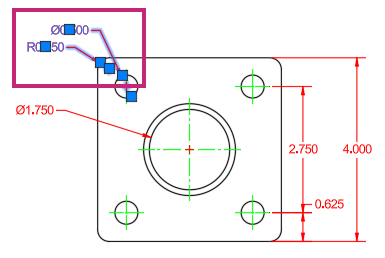
- In the drawing area, right-click and choose Properties.Find
On the Properties palette, under the Text section, click the Text Override field and enter 4X <>.
<> represents the measured value of the dimension.

On the Properties palette, click Close to hide the palette.
Press Esc to deselect the selected dimensions.
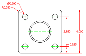
Finish dimensioning the top view based on the dimensions in the following image.
If needed, move the label for the top view and the objects of the side view downward to provide more room to place the dimensions below the top view.

- On the Quick Access toolbar, click Save.Find
Exercise 11: Plot the square flange design
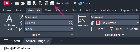
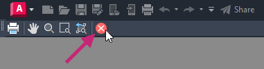
Plot/print the square flange views to a PDF file so that others without AutoCAD access can see the design.- On the Quick Access toolbar, click Plot.Find
If the Batch Plot task dialog box is displayed, click Continue to Plot a Single Sheet.

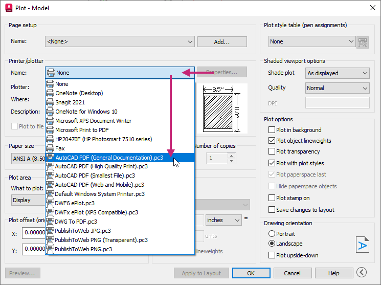
In the Plot - Model dialog box, under Printer/Plotter, click the Name drop-down list and choose AutoCAD PDF (General Documentation).pc3.
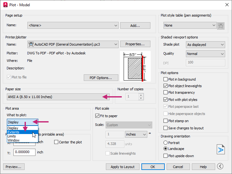
Under Paper Size, click the drop-down list and choose ANSI A (8.50 x 11.00 Inches).
Under Plot Area, click the What to Plot drop-down list and choose Extents.
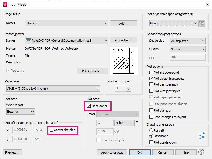
Under Plot Offset (Origin Set to Printable Area), select Center the Plot to turn the option on.
Under Plot Scale, select Fit to Paper to turn the option on.
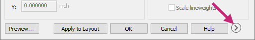
Click More Options to expand the dialog box.
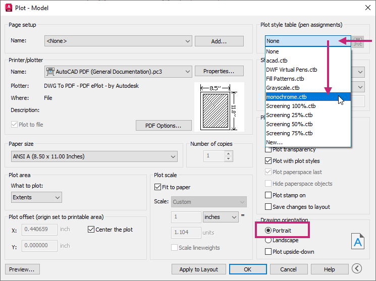
Under Plot Style Table (Pen Assignments), click the Plot Style Table drop-down list and choose monochrome.ctb.
In the Question message box, click No.
Under Drawing Orientation, select Portrait.
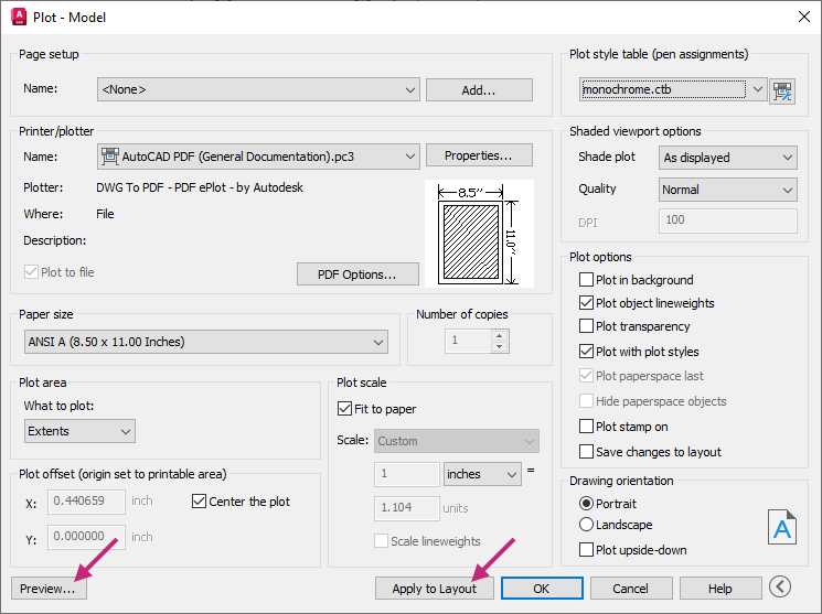
Click Apply to Layout to save the changes made to the plot settings and then click Preview.
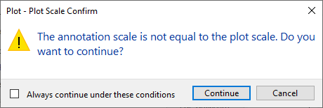
If the Plot - Plot Scale Confirm message box is displayed, click Continue.
In the Preview window, click and drag to increase and decrease the size of the preview. Right-click and use the shortcut menu to switch between the Zoom and Pan tools.
Press Esc or click Close Preview Window to return to the Plot dialog box.
In the Plot - Model dialog box, click OK.
If the Plot - Plot Scale Confirm message box is displayed, click Continue.
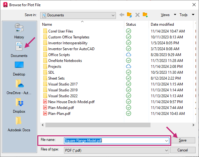
In the Browse to Plot File dialog box, browse to the Documents folder or a different location, and then provide a filename for the PDF file. Click Save.
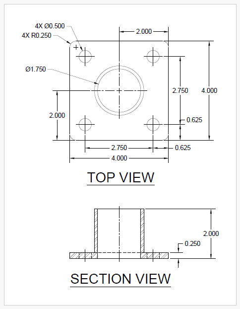
Review the PDF file if it automatically opens, otherwise open and review the file from Windows File Explorer.
Return to AutoCAD.
On the status bar, close the Plot and Publish Job Complete notification.
- On the Quick Access toolbar, click Save.Find
Summary
Congratulations on finishing the exercise! You've made great progress in mastering AutoCAD's essential tools and techniques. By completing exercises, like the "Mechanical Design: Square Flange Plate," you are well on your way to learning key design methods.
You have learned how to open and create drawings, modify 2D objects, use layers, apply hatches and fills, add annotations, center marks, and dimensions, insert blocks, and plot drawings to PDF files. These skills are crucial for creating precise and confident designs.
As you continue to practice and apply these techniques, you'll find yourself more proficient and capable in your AutoCAD projects. Remember, the key to mastery is consistent practice and application. Keep exploring, learning, and designing with confidence!
For more information on the concepts covered in the exercises of this topic, see:
- Create, Open, Save, and View Drawings
- Create Basic 2D Objects
- Create Objects with Precision and Accuracy
- Select, Modify, and Duplicate Objects
- Change Object Properties and Organize Objects with Layers
- Place Annotation and Hatch Closed Areas
- Add Dimensions to a Design
- Organize and Output a Design with Layouts