In this exercise you learn how to use separation tables to control the assignment of lines to layers when converting raster lines to vector.
The layer for the new vectors can be controlled by the raster line width or linetype (continuous vs. non-continuous). These layer controls are generally used for basic vector objects, such as lines and circles, and the polyline follower. When you are converting text or contours, other types of layer control can apply.
Related Exercises
Exercise
- In the
..\Program Files\Autodesk\ApplicationPlugins\RasterDesign2026.Bundle\Contents\Tutorials\Tutorial6 folder, open the drawing file
VTools_05.dwg.
Access the Raster Design Quick Bar
- Ensure that the Raster Design Quick Bar is visible. If it is not, at the Command prompt, enter iqbar.
- On the
Raster Design Quick Bar, clear the
Stop At Raster Intersections option
 .
.
Change the raster entity detection settings
- To display the
Raster Design Options dialog box, on the ribbon, click
Raster Tools tab
 Vectorize & Recognize Text panel Dialog box launcher (
 ).
).
- In the
Raster Design Options dialog box, click the
Raster Entity Detection tab and change the
Max Jump Length option to
70.
This setting specifies the maximum length of a gap that AutoCAD Raster Design toolset will tolerate when following a raster polyline. It can be used to jump over labels embedded in the line or to follow non-continuous lines such as dashed lines. This length is in pixels and can be selected on the screen using the Pick button.
- Change
Max Dash Length to
50 and
Max Blank Length to
20.
These settings control how AutoCAD Raster Design toolset detects the presence of dashed or non-continuous linetypes.
Change the vector separation settings
- Click the VTools General tab, then click Vector Separation to display the Vector Separation Options dialog box.
- Click the General tab and select
Override Width Table For Non-continuous Entities. In the Layer list, change the
Layer to
easement lines.
With this setting, lines detected as non-continuous will be placed on the easement lines layer.
Add width table entries
- Select the
Use Width Table option.
This setting allows you to specify layers based on ranges of widths in pixels for raster linework. When using the vectorization tools, the width of the raster selected is compared to the width table, and the layer is assigned based on these settings.
- Click Insert Below to add a range.
- Click
Query Width and select a point in a utility line to determine its width in pixels.
- Click OK to exit the Entity Width Information dialog box. In the Width Table, click on the new range once to activate it, then click on the Maximum value, and change it to 4.
- Click on the range once to activate it again, then click on the Layer setting. Use the drop-down list to change the layer to s-util for thin raster lines.
- Click
Insert Below to add another range.
Note that the new range is set to accept wider lines.
- Click on the new range once to activate it, click on the
Layer setting, change the layer to
*PROMPT*.
This setting forces the vectorization tools to prompt for a layer when thick raster selections are encountered. This option is very useful when several different types of lines have similar appearances in the raster file, but should be separated on different layers in the vector file.
- Click
OK to exit the
Vector Separation Options dialog box and then click
OK again to exit the
AutoCAD Raster Design Options dialog box.
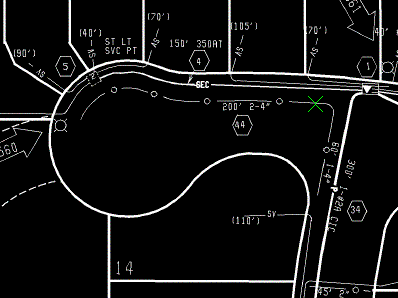
Convert a dashed raster line to vector
- To create a new polyline, on the ribbon, click
Raster Tools tab
Vectorize & Recognize Text panel
Followers drop-down menu
Polyline Follower
 .
.
- Click the lower left end of the bottom easement line to convert it to a polyline. The entire line is highlighted.
- Press
Enter to accept the polyline.
The new polyline is placed on the easement lines layer.
- Press
Enter again to exit the command.
Convert raster lines with differing widths to vector
- To create a new polyline, on the ribbon, click
Raster Tools tab
Vectorize & Recognize Text panel
Followers drop-down menu
Polyline Follower
.
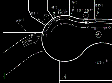
- Click the left end of the utility line inside the cul-de-sac to convert it to a polyline.
- Press
Enter to accept the polyline and start another.
The new polyline is placed on the s-util layer.
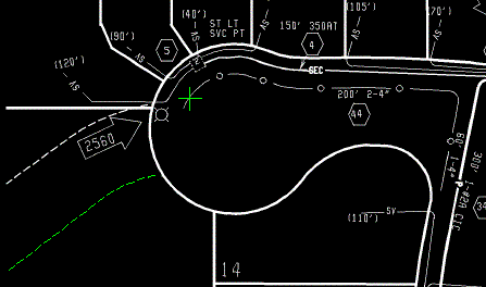
- Click on the bottom end of the short right-of-way line.
- When the follower reaches the end of the right-of-way, press Enter to complete the polyline.
- From the Select Layer dialog box, select the row layer, and then click OK.
- Press Enter to exit the command.
- From the
Raster Design Quick Bar, select the Stop At Vector Intersections option
 .
.
- To create a new line using the single pick option, on the ribbon, click
Raster Tools tab
Vectorize & Recognize Text panel
Primitives drop-down menu
Line
 .
.
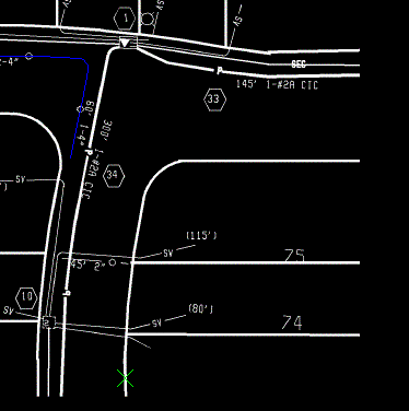
- Click the line between lots 74 and 75 and zoom to the area.
The following example shows where to select the point on the lot line to convert it to a vector.
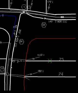
- When prompted, select the lot lines layer for the new line, and click OK.
- Press
Enter twice to exit the command.
The command removes the raster information below the new line.
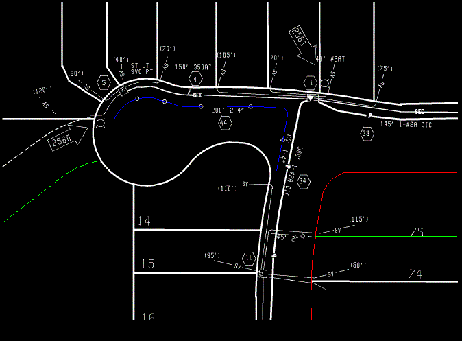
The following example shows how the drawing should appear after the various types of lines have been converted and placed on the appropriate layers.
- Close the drawing without saving changes.