In this exercise you learn how to use REM commands to modify a raster image.
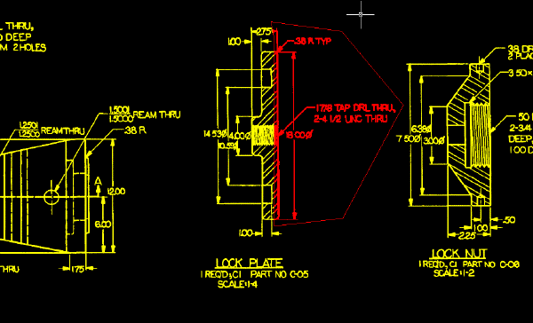
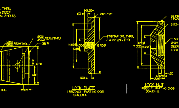
You will modify a lock plate that is part of a drill jig, increasing the back plane thickness of the lock plate, then updating the dimension text to reflect the change in thickness.
Related Exercises
Before doing this exercise, you should ensure that AutoCAD Raster Design toolset options are set as described in the exercise Exercise A1: Setting AutoCAD Raster Design Toolset Options.
Exercise
- In the ..\Program Files\Autodesk\ApplicationPlugins\RasterDesign2026.Bundle\Contents\Tutorials\Tutorial3 folder, open the drawing file REM_05.dwg.
- On the ribbon, click
View tab
 Named Views panel
View Manager
Named Views panel
View Manager
 . Then expand the
Model Views node and select the view named
TU_lock_plate, click
Set Current, and click
OK.
. Then expand the
Model Views node and select the view named
TU_lock_plate, click
Set Current, and click
OK.
Separate the lock plate into two pieces
- On the ribbon, click
Raster Tools tab
REM panel
Create Region drop-down menu
Polygonal Region
 .
.
- Draw a polygon with a vertical line that bisects the thinnest area of the lock plate and includes the dimension text to the right of the part. Press Enter.
- Enter
m and move the REM object exactly 0.25 inches to the right. To do this, use the
Displacement option and specify the displacement as
0.25,0,0.
This action creates a gap in the raster image. You must merge the region object into the image before you can make other changes to the part.
- Select the region object, right-click, and click
Merge to Raster Image from the shortcut menu.
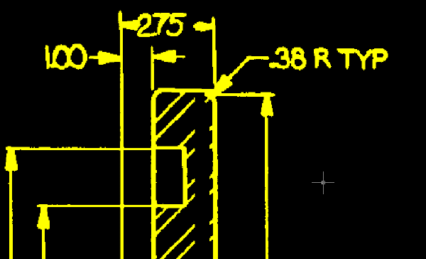
Close the top horizontal line
- On the ribbon, click
View tab
Named Views panel
View Manager
. Then expand the
Model Views node and select the view named
TU_2.75, click
Set Current, and click
OK.
- On the ribbon, click
Raster Tools tab
REM panel
Create Primitive drop-down menu
Line
 . Select the horizontal line at the top of the lock plate.
The line becomes a primitive object.
- Select the primitive object, select its right grip, and stretch the line to close the 0.25 inch gap.
- Select the primitive object, right-click, and click
Merge to Raster Image.
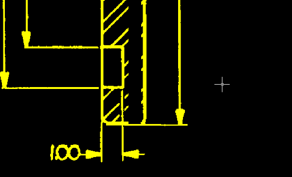
Close the bottom horizontal line
- On the ribbon, click
View tab
Named Views panel
View Manager
. Then expand the
Model Views node and select the view named
TU_bottom, click
Set Current, and click
OK.
- On the ribbon, click
Raster Tools tab
REM panel
Create Primitive drop-down menu
Line
. Select the horizontal line at the bottom of the lock plate.
The line becomes a primitive object.
- Select the primitive object, select its right grip, and stretch the line to close the 0.25 inch gap.
- Select the primitive object, right-click, and click
Merge to Raster Image.
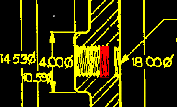
Close the thread lines
- On the ribbon, click
View tab
Named Views panel
View Manager
. Then expand the
Model Views node and select the view named
TU_thread, click
Set Current, and click
OK.
- On the ribbon, click
Raster Tools tab
REM panel
Create Region drop-down menu
Rectangular Region
 .
.
- Draw a narrow rectangle around some of the thread lines.
You can then copy this object to close the gap in the thread lines.
- Use COPY to copy the region object.
- Place the copy of the region object so that it closes the gap in the thread lines.

- Select the copy of the region object, right-click, and click Merge to Raster Image.
- Right-click and click
REM
Clear All from the shortcut menu.
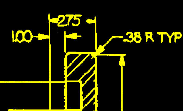
Replace the dimension text
You will now change the dimension text from 2.75 to 3.00 to indicate the new thickness of the lock plate.
- On the ribbon, click
View tab
Named Views panel
View Manager
. Then expand the
Model Views node and select the view named
TU_2.75, click
Set Current, and click
OK.
- Use the Layer Properties Manager to set TU_image_new as the current layer.
- On the ribbon, click
Raster Tools tab
Vectorize & Recognize Text panel
Text drop-down menu
Text
 . Then select a point at the base of the numeral 2 on the left.
The crosshairs identify where to select a point for placing new dimension text.
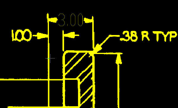
- In the VText Edit dialog box, enter
3.00 and click
OK.
AutoCAD Raster Design toolset places the new dimension text at the point you selected. On the command line, note that you are presented with a Smart Window option for removing the raster text. You will next use this method to remove the raster text 2.75.
- Draw a window around the old dimension text. It does not matter if part of the arrowheads are included within the window; they are excluded by the smart selection method. Note that the text about to be removed is highlighted. Press Enter to remove the selected text, then press Enter again to end the command.
- Select the vector text, then right-click, click Properties, and change the Width Factor of the text to 0.8.
- Center the dimension text between the leader arrows if necessary.
- To open the
Raster Pen Settings dialog box, on the ribbon, click
Raster Tools tab
Edit panel (expanded)
Raster Pen
 .
.
- Select Yellow, change the units to AutoCAD, and click Pick.
- Select two points representing the width across the vertical dimension line.
The following example shows where to select the two points that determine the raster pen width for the new dimension text. When you create raster text from the vector dimension text, the thickness of the text should be comparable to the line work in the image.
- Verify that Pen Width is set to approximately 0.10 and click OK.
- Select the vector text, then right-click and click Merge Vector To Raster Image.
- Enter
y (Yes) to delete the vector text after the merge.
The following example shows how the image should appear after you replace the old dimension text with new raster text created from vector dimension text.
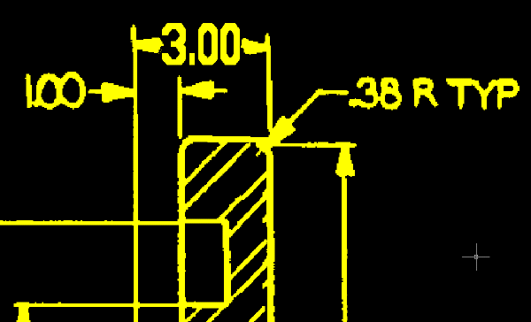
Review the Changes to the Lock Plate
- On the ribbon, click
View tab
Named Views panel
View Manager
. Then expand the
Model Views node and select the view named
TU_lock_plate, click
Set Current, and click
OK.
- Review the changes to the part and its dimensions.
This example shows how the lock plate and its dimension text should appear after you update them.
- Close the drawing without saving changes.