Create weld bead features in weldments
In a weldment assembly, use commands on the Weld tab to create fillet welds, groove welds, and cosmetic welds. Create intermittent or continuous fillet welds along the length of selected faces or use a groove weld to connect two faces with a solid weld bead.
The following images show cosmetic, fillet, and intermittent fillet welds.
Weld bead features are always affected by post-weld machining features, but are not affected by weld preparation features. Weld bead features are also not included in assembly feature participation lists.
You can create a welding symbol when you create a weld bead or you can create it in a separate operation.
Create a fillet weld feature
Fillet welds build up corners by adding material between one or more faces of a single part or multiple parts.
In a weldment assembly, double-click the Welds group in the browser to activate it.
On the ribbon, click Weld tab
 Weld panel Fillet to open the Fillet Weld dialog box.
In the graphics window, select one or more faces for the first selection set. Use the Shift key to cancel the selection of unwanted faces.
Right-click and select Continue, and then select the second set of faces in the graphics window.
If necessary, select the Chain check box to chain the faces together.
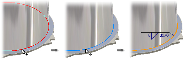
Select the orientation of the weld bead and then enter corresponding values for the bead legs.
Click the arrow to select the bead contour.
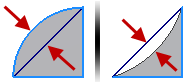
If you choose a Convex or Concave contour, the Offset value is available. This value describes the amount the curve is offset from the flat as shown in the following image. The preview in the graphics window updates with the entered values.
If creating an intermittent bead, set values according to the active standard. The preview image shows where the values are applied.
Under Extents, click the down arrow and select the method to terminate the weld.
- Use Extents All to cut through all faces. If some faces are removed from the feature, All remains a valid termination method because it does not rely on a specific distance or face.
- Use Extents From-To only if you are sure the beginning and ending faces (or planes) remain intact throughout design changes. If the From or To face (or plane) disappears, the feature fails. Click the Start and End termination planes or faces. Selected termination planes and faces must be parallel.
- Use Extents Start-Length when you want to specify a start point with or without an offset value and the overall length of the weld bead. Use Start-Length if the weld does not begin or end on an edge. Reverse the start point by selecting the Direction icon.
If appropriate, click the Create Welding Symbol check box. Fillet weld beads are linked to values in the welding symbol unless you specifically break the link. Enter values to define the content and appearance of the welding symbol.
For more information about the meaning of values in the welding symbol, see the Model welding symbol reference.
Click Apply to create the fillet weld bead and, if selected, the welding symbol. Continue to create beads, if desired, or click Cancel to close the dialog box.
Create a groove weld feature
In a weldment assembly, double-click the Welds group in the browser to activate it.
On the ribbon, click Weld tab
Weld panel Groove to open the Groove Weld dialog box.If required, select the Chain Faces check box to pick multiple tangent faces.
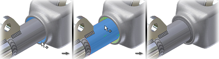
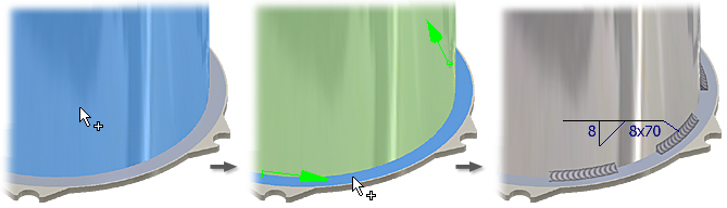
Click Face Set 1, and in the graphics window select one or more faces for the first selection set. Use the Shift key to cancel the selection of unwanted faces. The selected faces match the colored line on the button face.
- Select the Full Face Weld check box if you want the weld bead to extend the full length of the selection set.
- Select Chain Faces to include all tangent faces in the selection.
- Select the Ignore Internal Loops check box to extend the weld bead across internal loops, such as holes or cuts.
Right-click and select Continue and then select the second set of faces in the graphics window. Selected faces match the colored line on the button face.
Select Full Face Weld and Ignore Internal Loops check boxes to specify the treatment for the second selection set.
Click Fill Direction. In the graphics window, click an edge or face to indicate the weld direction.
If a direction pick is not required, such as a cylinder in a hole, select the Radial Fill check box to define the direction.

If required, click the Create Welding Symbol check box. Enter values to define the content and appearance of the welding symbol.
For more information about the meaning of values in the welding symbol, see the Model welding symbol reference.
Click Apply to create the groove weld bead and, if selected, the welding symbol. Continue to create beads, if desired, or click Cancel to close the dialog box.
Create a cosmetic weld feature
Open a weldment assembly. If necessary, convert a regular assembly to a weldment. For more information, click Convert an assembly to a weldment.
In the browser, right-click the Welds folder and select Edit.
On the ribbon, click Weld tab
Weld panel Cosmetic .Specify the Select Mode. Select one or more edges, or select a chain of contiguous edges or a closed loop.
Under Extents, click the arrow to select the method to terminate the cosmetic weld bead:
- Use All to cut through all faces. If some faces are removed from the feature, All remains a valid termination method because it does not rely on a specific distance or face.
- Use From To only if you are sure the beginning and ending faces (or planes) remain intact throughout design changes. If the From or To face (or plane) disappears, the feature fails. Click the Start and End termination planes. Selected planes and faces must be parallel.
In Area, click to select the area or use the Measure command or Show Dimensions.
Select the Create Welding Symbol check box to create the welding symbol together with the cosmetic weld bead. For more information, click Model welding symbol reference.
If you prefer, you can create the weld symbol later. The cosmetic weld bead is nested below the weld symbol in the browser Weld folder.