To Define and Manage Joint Relationships
Each joint type fully defines the location and motion of the selected components. You can select end, mid, or center point geometry (including the center point of a slot) to define a joint. You can also set the joint relationship conditions using Lock and Protect.
On the ribbon, use Assemble tab  Relationships panel Joint
  to place a joint between two assembly components.
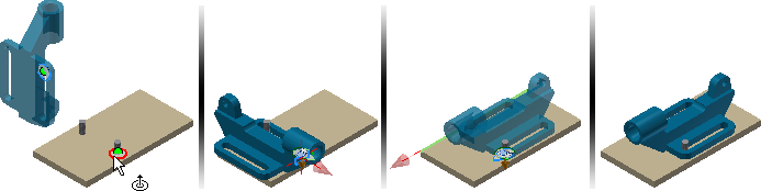
Use Joint to position components and define motion
To begin, place the components in an assembly file.
Start the Joint command.
The default connection type is Automatic. Automatic determines the joint type based on the following rules:
Rotational is selected if the two selected origins are circular.
Cylindrical is selected if the two selected origins are points on a cylinder.
Ball is selected if the two selected origins are points on a sphere.
Rigid is selected for all other origin selections.
Note: A Slider connection cannot be specified using a selection rule.
 Select the origin on the moving component.Tip: Click Ctrl after the necessary component highlights to limit selection to the component.
The default origin selection is inferred directly from the geometry. For origin that cannot be inferred directly, make a selection from the context menu:
- To create a joint origin between 2 faces, select Between Two Faces, and specify a virtual midpoint between two faces, by selecting two faces and one point.
- To create a joint origin and position it an offset distance from the origin, select Offset Origin. Drag the manipulator arrows or input offset value to change the Origin location. Pick a reference geometry to align the Origin with.
 Select the origin on the stationary component.
If necessary, change the joint type.
 If necessary, use Flip component to reverse the positive direction.
 If necessary, select Align 1 and pick one of the following to specify the alignment direction:
- A planar face, point, or edge on the moving component.
- A work plane/work axis/work point from the browser or the graphic window(if visible). If Align 1 is point selection(sketch point or work point), Align 2 must also be point selection.
 If necessary, select Align 2 and make a selection on the stationary component to specify the alignment direction.
 To change the alignment direction, select Invert alignment.
lick Apply or OK to complete the operation.
Use Limits to define range of motion
To define a limit:
Create or edit a joint.
Open the dialog box. and click the Limits tab.
Tip: If the dialog box is not available, press the three dots in the min-toolbar to display.The availability of the Angular or Linear options depends on the joint type. For example, a Rotational joint supports Angular limits, but Linear limits are not available.
Note: Limits are not available for Rigid joints.Set the necessary Start, Current, and End values.
Click OK.
A relationship with a defined limit is marked with a +/- symbol in the browser.
Lock or Protect joint
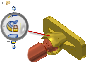
- Lock a relationship to maintain the current position. Lock differs from grounding a component. Grounding eliminates all degrees of freedom, and fixes the component position in space. Lock eliminates all motion, but allows the component to change position when related components move.
- Protect a relationship to warn if added relationships violate the necessary degrees of freedom.
Lock or Protect relationship:
- Locate the relationship in the browser.
- Right-click the relationship, and select Lock or Protect in the context menu.
- To remove the condition, clear the check mark.
Edit or modify joints
To edit a joint, double-click the joint in the model browser or double-click the joint glyph in the graphics area.
To modify a joint, select the joint in the model browser then modify the value in the edit field.