To Create a Draft
You can create a fixed edge or fixed plane face draft, or a parting line face draft
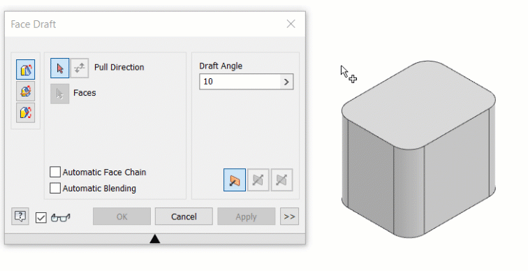
The Draft feature applies a taper to part faces to cant a surface or allow a part to be extracted from a mold. Draft is defined by specified faces, pull direction, angle, and fixed edge or tangent surface. You can create three types of drafts in Inventor: Fixed Edge, Fixed Plane, or Parting Line.
To begin, create a 3D part with faces or edges to draft.
Create a Fixed Edge or Fixed Plane Face Draft
The following steps detail using the Fixed Edge and Fixed Plane options in the draft command. The third option, Parting Line, is detailed in the next section.
Click 3D Model tab
 Modify panel Draft
  .
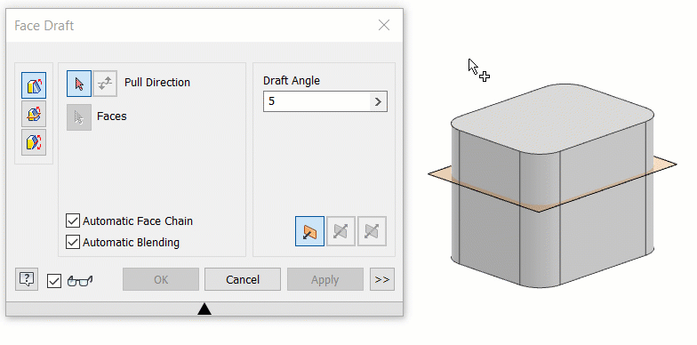
.In the Face Draft dialog box, select one of the following the draft types:
Fixed Edge
 . Creates draft about one or multiple tangent contiguous fixed edges per face. Result creates more faces.
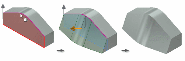
Fixed Plane
 . Creates draft about a fixed plane. The planar part face or work plane determines which selected faces are drafted. Depending on the position of the fixed plane, the draft can both add and remove material.
In the following example, the fixed top face sets an upward pull direction. All side faces are drafted, adding material below the fixed plane.

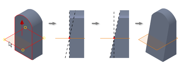
In another example, a work plane is the fixed plane. Material is removed in the pull direction above the fixed plane and added below the fixed plane:
Define the pull direction: Move the cursor over a face, work plane, edge, or axis, until the direction arrow aligns with the appropriate pull direction. Then click to select.
Tip: To change the pull direction, click Flip Direction .
.Select the faces to draft. As you move the cursor over a face, it highlights in one color, and the fixed edge, which is the intersection of the selected face and the fixed plane, highlights in a second color. To remove a face or edge from the selection set, press Ctrl + click.
Note: If a face is tangent to other faces, all tangent faces highlight. To select individual faces, disable Automatic Face Chain.Specify values for the angle and the symmetry:
- Draft Angle and Draft Angle 2. Sets the angle of the draft. Enter a positive or negative angle, or choose a calculation method from the list.
- One Way
 . Adds draft in a single direction. Available for fixed edge and fixed plane types.
 - Symmetric
 . Adds draft above and below the plane or parting line. Uses the same angle value. Available for fixed plane and parting line draft types.
 - Asymmetric
 . Adds draft above and below the plane or parting line. Uses a different angle value for the upper and lower draft. Available for fixed plane and parting line draft types.
To maintain adjacent blended features, such as fillets, select Automatic Blending. To stop the blended features from participating in the draft, turn off Automatic Blending.
Click OK.
Create a Parting Line Face Draft
The parting line face draft option lets you explicitly define which part of the model thickness to preserve.
On the ribbon, click 3D Model tab
Modify panel Draft .Click the Parting Line draft type
 .
.Define the pull direction. Move the cursor over a face, work plane, edge, or axis, until the direction arrow aligns with the appropriate pull direction. Then click to select.
If necessary, to change the pull direction, click Flip pull direction.
Select the Parting Tool. The parting tool can be a sketch, plane, or surface.
Select the faces to draft. As you move the cursor over a face, it highlights in one color, and the fixed edge highlights in a second color. To remove a face or edge from the selection set, press Ctrl + click.
Note: If a face is tangent to other faces, all tangent faces highlight. To select individual faces, disable Automatic Face Chain.To maintain adjacent blended features, such as fillets, use Automatic Blending. To stop the blended features from participating in the draft, disable Automatic Blending.
Enter the draft angle.
Click OK to finish or follow the remaining steps to define static edges.
1, Select the Move Parting line option in the dialog box.
If desired, enable the Static Edges selector and select the individual fixed edges or click Select Boundary to select multiple edges automatically.
Click Clear All to remove all edges from the selection set.
Enable one of the following options:
- Angle for Top
- Angle for Both
- Angle for Bottom
Optionally, expand the dialog box and set the Draft Angle to Absolute or Relative.
Click OK.
How to Use Automatic Face Chain and Automatic Blending with Face Draft
How to Create a Fixed Plane Face Draft