To Create Revolved Features
Learn the workflows to create revolved features: from a face, sketch profile, or from a primitive.
The two primitive shape creation commands, Torus and Sphere, create full revolutions only. They do not create surfaces or partial revolutions.
Presets are hidden by default. If you want to create extrusion presets for commonly used shapes, in the Advanced Settings menu, uncheck Hide Presets. To learn more about presets see To Work with Presets.
Create a Revolved Feature
Revolved features can be a base feature, that is the first feature, or an auxiliary feature used to define the component.
Starting without a profile sketch
- On the ribbon, click 3D Model tab
 Create panel Revolve
  . The Sketch command starts and the Origin workplanes display.
 - Click on a workplane. A sketch is created on that plane and the Sketch tab is displayed.
- Using the Sketch commands, draw the profile you want to revolve.
- Sketch or project an axis if not using an Origin axis.
- Click Finish Sketch. The Revolve command property panel displays and previews the result.
- Specify the Feature Type.
For the next steps see Define the Revolve Feature Using the Property Panel, below.
Starting with a profile sketch
The sketch containing the profile you want to revolve must be visible or active. Valid geometry can be:
- A new sketch, with one or more profiles, that have not been used to create any features.
- A sketch with geometry that creates one or more closed regions. Geometry can be projected into the sketch to create profiles or regions.
- An existing sketch that has been consumed by a feature and is visible when the command is initiated. The Advanced menu option Keep sketch visible on (+) is on by default.
- No sketch, no problem! The sketch command starts. Click on a workplane or face and begin sketching.
On the ribbon, click 3D Model tab Create panel Revolve . For the next steps see Define the Revolve Feature Using the Property Panel, below.
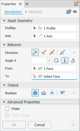
Define the Revolve Feature Using the Property Panel
At the top of the property panel is the breadcrumb. You begin with feature definition but can quickly move between feature definition and editing the sketch by clicking the breadcrumb sketch text. Return to the feature environment by clicking the breadcrumb feature text.
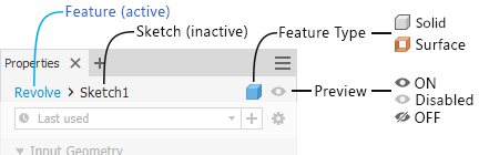
To the right of the breadcrumb is the feature type. The type determines which options are presented in the property panel.
Specify the feature type:
 Solid (default) - Creates a solid feature from an open or closed profile. Open profile selection is not available for base features.
 Surface - Creates a surface feature from an open or closed profile. The feature functions as a construction surface on which to terminate other features, or a split tool to create a split part, or split a part into multiple bodies. Surface selection is not available for assembly revolves or primitives.
Click the icon to switch to the other feature type.
(Optional) If you have presets for revolved features and want to use one, click the Advance Settings menu and select Hide Presets (default is checked) to uncheck the option and show the Presets controls.

Specify the Input Geometry. You can use window select to quickly select multiple closed profiles within the same sketch.
Important: During feature preview visible sketch dimensions can be edited without entering the sketch environment.Profiles - the Profiles selector is active by default and when there are:
For only one profile - the profile is automatically selected.
- Multiple profiles - select the profile, loop or region defining the revolved feature to create.
Note: For part features, you can use a shared sketch as a profile. To share a sketch:- In the browser, click the plus sign beside the feature that contains the sketch you want to use to expose the sketch node.
- Right-click the sketch icon and click Share Sketch. Any sketch that you use in more than one feature is automatically shared.
-Axis - right-click in the display and select Continue or click the property panel selector and then select an axis from the active sketch.
Specify the Behavior parameters.
Direction
 Default: Revolves in one direction only.
 Flipped: Revolves in the direction opposite of Direction (default).
 Symmetric: Revolves in opposite directions from the sketch plane, using half the specified Angle A value in each direction.
 Asymmetric: Revolves in opposite directions from the sketch plane using two values, Angle A and Angle B. Enter a value for each angle. Click
  Flip to swap the angle values.
Angle
Angle A: Specifies the revolve angle between start and end planes. Dragging the manipulator will modify the value at 5 degree increments.
Angle B: Specifies the angle for the secondary direction. It displays for the Asymmetric direction.
 Full: Revolves the profile a full 360 degrees.
 To: For part revolutions, requires an ending face or plane on which to terminate the revolution. If the termination face doesn't intersect the revolved feature, the face is extended automatically to create the feature. Use the Minimum Solution
  option to help resolve.
 Extend face to end feature - automatically activates when the To or To Next selection does not intersect the revolved profile. You can also manually turn on or off the option.
- Minimum Solution - when options for termination faces are ambiguous, specifies that the extrusion terminates on the closest face.
For assembly revolves, you can select faces and planes that reside on other components. To be selected, work planes and work points must reside at the same assembly level as the assembly revolve you are creating.
 To Next: Requires an intersecting body on which to terminate the revolve feature in the specified direction. Use the Terminator selector to select a solid on which to terminate the extrusion and the direction options for the revolved feature.
Note: Use the From and To options to get the same result as the Distance from Face and Between methods in prior releases.For multi-body parts, click the From Selector and select the participating body.
For non-base features, specify an operation:
 Join: Adds the volume created by the revolved feature to another feature or body. Not available in the assembly environment.
 Cut: Removes the volume created by the revolved feature from another feature or body.
 Intersect: Creates a feature from the shared volume of the revolved feature and another feature. Deletes material that is not included in the shared volume. Not available in the assembly environment.
 New Solid: Creates a solid body. Each solid body is an independent collection of features separate from other bodies. If desired, rename the body.
Advanced Properties
iMate (Optional) Places an iMate on a full circular edge. Autodesk Inventor attempts to place the iMate on the closed loop most likely to be useful. In most cases, place only one or two iMates per part.
Match Shape: If you select an open profile in a part file, specify whether you want to Match Shape and, if so, select the side to keep.
Selecting Match Shape creates a flood-fill revolved feature. The open ends of the profile are extended to the axis of revolution (if possible), or to the bounding box of the body. The Match Shape revolution generates a stable and predictable body for topology changes on the defining faces.
Clear the Match Shape option to close the open profile by extending the open ends to the part, and closing the gap between them. The revolution is created as if you specified the closed profile.
Click OK or
 (Create new feature) to continue defining revolved features.
Create Revolved Feature from a Primitive
Click 3D Model tab
Primitives panel Sphere  or 3D Model tab Primitives panel Torus
  .
1`. Select a sketch plane. The sketch plane can be an origin plane, a work plane, or a planar face.
.
1`. Select a sketch plane. The sketch plane can be an origin plane, a work plane, or a planar face.Define the shape by doing one of the following:
- For a sphere, click to define the center and then click to define the diameter.
- For a torus, click to define the center, click to define the center of the section, and then click to define the diameter of the section.
If there are multiple bodies in the part file, click the Solids selector in the Shape tab of the Revolve dialog box to choose the participating body.
Specify an Operation:
- Join: Adds the volume created by the revolved feature to another feature or body. Not available in the assembly environment.
- Cut: Removes the volume created by the revolved feature from another feature or body.
- Intersect: Creates a feature from the shared volume of the revolved feature and another feature. Deletes material that is not included in the shared volume. Not available in the assembly environment.
- New Solid: Creates a solid body. Each solid body is an independent collection of features separate from other bodies. A body can share features with other bodies. If desired, rename the body.
(Optional) Advanced Properties section, select Infer iMate to place an iMate on a closed loop.
Click OK or
(Create new feature) to continue defining revolved features.
Editing a Revolved Feature
In the graphics window or the browser, right-click the feature and choose Edit Feature. You can double-click the browser node to edit the feature.
The property panel displays.
Change defining values, the method to terminate the feature, or whether it joins, cuts, intersects another feature, or is a new feature.
To Edit the feature sketch, in the property panel breadcrumb text, click the Sketch# and begin editing the sketch. For more information see To Create and Edit Sketches.