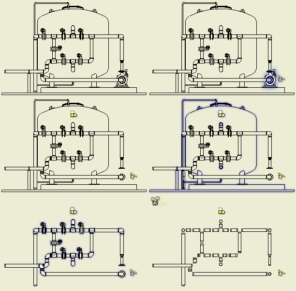
To Create and Edit Tube and Pipe Drawings

In the assembly environment, view representations, positional representations, and model states are typically prepared to meet the design needs beforehand. They can be associated to specific drawing views upon creation or later edits.
To create tube and pipe drawings, use standard drawing templates. Create appropriate drawing views to document the entire tube and pipe assembly or specific routes and runs, and then use appropriate drawing settings to annotate the drawing views.
Create tube and pipe drawing views
Click File
 New.
New.In the Open dialog box, select a drawing template, for instance, a custom predefined idw or dwg containing active tube and pipe standards.
The drawing environment is activated.
 Optionally, customize the drawing settings for this drawing document using the Manage tab
  Styles and Standards panel
  Styles Editor command. For instance, select appropriate column properties into the parts lists format and determine the grouping keys.
 On the ribbon, click Place Views tab
  Create panel
  Base . Select the assembly file, design view representation, positional representation, model state representation, and assembly member where appropriate, and all other options.
Optionally, use appropriate drawing view commands to create other types of drawing views as you need.
In the Model browser, drawing views that are created from the base view are located underneath.
Enable and set tube and pipe bill of materials
1.![]() With a drawing view created, right-click the base view in the Model browser and select Bill of Materials.
With a drawing view created, right-click the base view in the Model browser and select Bill of Materials.
 In the BOM Editor, click the Structured or Parts Only tab, click the down arrow next to View Options, select Enable BOM View, and optionally edit view properties.
With either the Structured or Parts Only tab active, do any of the following:
Override field values in the Bill of Materials table.
Add custom iProperty columns.
Select the columns into or out of the Bill of Materials table.
Renumber item rows.
Add the bill of materials to the notes in the Engineer's Notebook.
Export a bill of materials to an external database, spreadsheet, or text file.
Note: To export specific routes and runs rather than the entire tube and pipe assembly, set the unwanted routes and runs to Referenced in the BOM Structure column.
Click Done.
Changes to the Bill of Materials table are automatically reflected in parts lists with an exception of static fields.
Roll up tube and pipe components in parts lists
 On the ribbon, click Annotate tab
  Table panel
  Parts List .
If BOM views have not been enabled, system prompts you whether you want to enable BOM views. Click Yes to continue.
In the Parts List dialog box, select the drawing view in the graphics window, and set the appropriate BOM view properties and table wrapping properties.
Click OK and place the parts list at an appropriate position.
 To make adjustments, right-click the parts list and select Edit Parts List. For instance, use the Column Chooser command to select additional columns to the parts list.Note: For detailed information about available edit options, see Modify the data in a parts list.
 To modify the parts list format, right-click the parts list and select Edit Parts List Style.
Optionally, to save all changes in the parts list back to the assembly global BOM, right-click the parts list and click Save Item Overrides to BOM.
Tip: To move the parts list in drawing document rigidly, move the cursor over the parts list and ensure the following symbol is attached to the cursor. Drag it to a new position and release the cursor.
Annotate tube and pipe drawings
On the drawing Annotate tab, Autodesk Inventor provides the same set of drawing annotation commands as with normal Inventor drawings. For instance, place balloons and symbols to represent tube and pipe components. Optionally, you can use Manage tab  Styles and Standards panel
  Styles Editor to customize styles and formats.
In addition, you can reference the information that is set up in tube and pipe styles and use the information to annotate drawing views. For detailed instructions, see Annotate tube and pipe drawings with tube and pipe styles.