To Create Patch, Stitch, or Ruled Surfaces
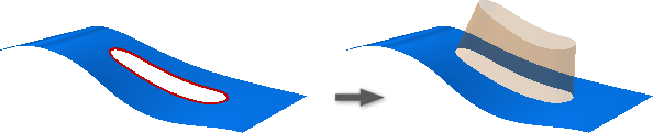
Create a Boundary Patch from a 2D Sketch
Generate a planar or 3D surface from a closed 2D sketch, a closed boundary, or a mixture of both. Start with a 2D sketch that includes a single loop, multiple loops, intersecting loops, or islands. All loops selected in a single operation create one profile.
Click 3D Model tab
 Surface panel Patch
  .
.In the graphics window, select the profile for creating a boundary patch. If necessary, use Select Other to cycle through selectable geometry, and then click to select.
Tip: If the sketch contains overlapping loops, you can choose the region outside the nested loop.Note: You can’t apply boundary conditions to sketches.
Click OK.
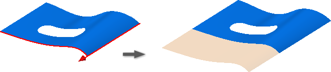
Create a Boundary Patch from a Chain of Edges
Generate a boundary patch from a closed loop.
Click 3D Model tab
Surface panel Patch .Click in the graphics window to select a chain of tangent or continuous edges that define a closed loop.
Note: Region selection is limited to planar patches. For nonplanar regions, select the first loop. Use Select Other to cycle through selectable geometry, and then click to select.In the Boundary Patch dialog box, under Condition, specify a boundary condition for each edge or set of selected edges.
Note: Continuous edges must have the same edge condition. Thus, all selected surface edges that are tangent or smooth with the previous edge merge, and display as a single edge. Edges selected with Automatic Edge Chain turned on also display as a single edge in the Condition panel. To apply a specific condition to each edge, turn Automatic Edge Chain off. Contact (G0). Default.
 Tangent (G1).
 Smooth (G2).
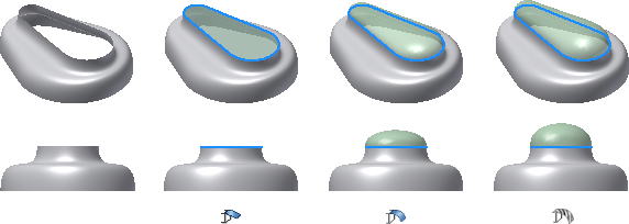
For G1 and G2 edge conditions, specify a Weight.
Weight is a unitless factor that influences the shape of the boundary patch. Typical weight factors range from 0 to 1.
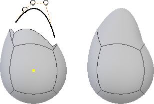
Optionally, select Guide Rails and then select one or more curves or points to shape the patch.
Optionally, select another closed loop.
Click OK.
Stitch Surfaces Together
Use the Stitch feature in the part environment to stitch surfaces together into a quilt.
Click 3D Model tab
Surface panel Stitch  .
.Using the Surfaces selector in the Stitch dialog box, select surfaces using one of the following methods:
- To select all surfaces at once, right-click and click Select All.
- To select one or more individual surfaces, click them in the graphics window.
Click the Analyze tab of the Stitch dialog box to enable the display of edge conditions so that you can assess edges before stitching together:
- Show Edge Conditions. When selected, black indicates surface edges that are stitched to an adjacent surface. Red indicates surface edges that are not stitched.
- Show Near Tangent. When selected, shows near-tangent conditions in magenta. Near-tangent edges can cause failures in subsequent design operations, such as creating a shell. However, enabling tangent edge analysis decreases system performance.
Click the Stitch tab and specify a Maximum Tolerance allowable between free edges.
Select Maintain As Surface to maintain a closed volume as a surface. If not selected, a closed volume that results from the stitch operation becomes a solid.
To join surfaces together in a quilt or solid, click Apply.
After stitching, the Find Remaining Free Edges list displays the remaining free edges and the maximum gap between them. Free edge pairs that partially exceed the maximum tolerance display the minimum gap in red (meaning that the gap is within tolerance but not fixed). Free edges without pairs display no gap value.
Adjust the tolerance to stitch surfaces that were unsuccessful the first time: In the Maximum Tolerance list, select or enter a value. Look at the remaining edge pairs that you want to stitch together and identify the smallest associated Max Gap value. The Max Gap value is the largest gap that the Stitch command considers for making a tolerant edge. Use the smallest Max Gap value as a guide for entering a Maximum Tolerance value. For example, a Max Gap of 0.00362 must have a value of 0.004 entered in the Maximum Tolerance list to enable a successful stitch.
- Select a row item, right-click, and choose Find in Window to zoom in on the edge.
- Select a row, right-click, and choose Set as Tolerance to set that value as the Maximum Tolerance
Click Apply.
All the newly stitched edges are black.
Repeat steps 7 and 8 until stitching is complete, then click Done. All edges return to their original color before entering the Stitch command.
Note: By default, stitch features consume input surface features such as extruded or revolved surfaces. Consumed features are nested and indented below the consumer to show the dependency on that feature. In cases where consumption is not desirable, you can right-click in the browser, and then select Consume Inputs to change the consumption status.
Create a Ruled Surface
Create a ruled surface to add extensions to complex surfaces, create parting surfaces, or to add a drafted face that follows a direction vector.
Click 3D Model tab
Surface panel Ruled Surface  .
.In the dialog box, do one of the following:
Select Normal to create a surface normal to the selected edge.
Select Tangent to create a surface tangent to the selected edge.

Select Vector to create a surface that follows a selected face, work plane, edge, or axis.
In the graphics window, select the edges for creating a ruled surface. If necessary, use Select Other to cycle through selectable geometry, and then click to select.
Note: Sketch edges are not valid for ruled surface edge selection.Optionally, clear the check box to disable Automatic Edge Chain.
Optionally:
In the dialog box Selection panel, select the alternate face icon to change the source reference face for the edge.

To change the source reference face for all selected edges, click Alternate All Faces.
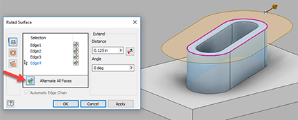
Note: The alternate face option is valid for selected edges that share two faces.- Optionally, pick Flip to change the direction of the surface.
- For the Sweep option, click a face, an edge, or an axis to specify the direction Vector.
- Set the distance to extend the surface.
- Optionally, specify an angle for the surface.
- Click OK to finish.