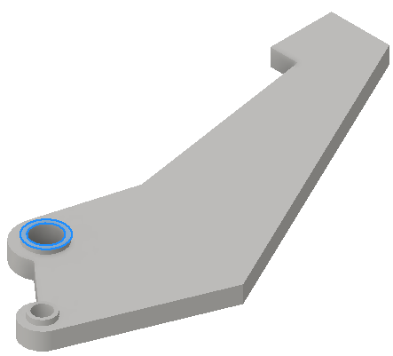
To Apply Constraints
In Shape Generator, apply constraints to remove all free translational and rotational movement of the body.
Structural constraints restrict or limit the displacement of the model. Add constraints to mimic environmental conditions. To do so, fix a face, for example, or combine partial constraints on faces, edges, or vertices.
- On the ribbon, Analysis tab
 Constraints panel, click a structural constraint:
Fixed 
Apply to a face, edge, or vertex. Removes all degrees of freedom, and prevents the face, edge, or vertex from moving or deforming.
Pin 
Apply to cylindrical faces. Prevents the faces from moving or deforming in combinations of radial, axial, or tangential directions
Frictionless 
Apply to a flat or cylindrical surface. Prevents the surface from moving or deforming in the normal direction relative to the surface.
or
In the browser, right-click the Constraints  node, and click the constraint type.In the dialog box, with Location
 active, select the constraint location..
For access to other constraint parameters, click
 (More). The available parameters are based on the constraint type.
Select the appropriate input for the constraint type. You can select more than one input only if the selections are of the same type, such as face, edge, or vertex.
For frictionless constraint
To apply a fixed constraint with non zero displacement:
- Click Use Vector Component
- Select the x, y, or z vector components that define your displacement vector
- Enter the appropriate displacement magnitudes for each vector component.
For Pin constraint
Fix Radial, Axial, or Tangential Direction Cylindrical surfaces cannot move, rotate, or deform radially, axially, or tangentially to the cylinder.
- Click OK.