Save As Export Options Reference
Whats New: 2022.2
Common Save As Export Options
Include Sketches
Select to include visible sketches in the exported file.
When you save a file as SAT, the sketches are translated to the SAT file without grouping information.
CATIA V5 Export Options (*.CATPart, *.CATProduct)
Version
Select the file format version for export.
IGES File Export Options (*.igs, *.ige, *.iges)
Results of exporting to IGES may be:
- Part geometry, surfaces, and wireframe from solids.
- Base surfaces are assigned to separate layers.
- Only visible surfaces in part modeling are exported.
Output Solids As
- Surfaces: the model is output as a collection of Nurbs surfaces.
- Solids: the model is output as a solid body.
- Wireframe: the model is output as a collection of wires.
Surface Type
- IGES 143: Bounded Surface. Mathematically more accurate than the older parametric surface type.
- IGES 144: Trimmed Surface. Available for systems that do not recognize bounded surfaces, or if conversion problems occur.
Solid Face Type
- Analytic: Faces retain their analytic characteristics. Supported face types are Planar, Cylindrical, Conical, Spherical, and Toroidal.
- NURBS: Use if faces do not meet analytical characteristics.
Spline Fit Accuracy
The accepted range for the value is from 0.00001 cm to 0.001 cm. A smaller value creates more accurate geometry approximations and larger file size. The value persists in current and later sessions until you change it. The value displays using the document units.
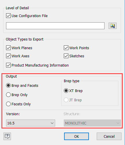
JT File Export Options
Use Configuration File
Check this box to use a pre-defined file that contains the export settings for the Output section. You can use this file to control LOD and other settings if the default export options do not provide the desired results. For example, you can adjust the chordal LOD values to affect larger features and angular LOD values to affect smaller features.
You can find a sample CFG file in [drive]:\Users\Public\Documents\Autodesk\Inventor [version]\Samples\Translation\[language]
The configuration file supports modifying the following areas:
- Brep and Facets:
- Brep and Facets: includeBrep = true, includeGeom = true
- Brep Only: includeBrep = true, includeGeom = false
- Facets Only: includeBrep = false, includeGeom = true
- Brep type:
- XT Brep: autoXtBrep = true
- JT Brep: autoXtBrep = false. Note: JT Brep type requires version 10.2 or older.
- Structure: (available for assemblies only)
- MONOLITHIC: structureOption = "MONOLITHIC" Tip: The assembly is stored in a single JT file.
- PER PART: structureOption = "PER_PART" Tip: The assembly hierarchy is stored in a single JT file, and each part is stored as a JT file in a subdirectory.
- FULL SHATTER: structureOption = "FULL_SHATTER" Tip: Each assembly component is stored in a unique JT file.
- Version: Example, Version 8.0 is written as JtFileFormat = "80", Version 10.5 is written as JtFileFormat = "105"
Product Manufacturing Information
Includes PMI data, typically manufacturing information attached to the 3D model, in the exported file.
Output
Select the output options.
Brep type
If you select Version 10.3 and above, JT Brep is not available.
Version
Select the file format version for export.
Structure
Available for assemblies only. Specifies a structure type and number of generated files to apply to the exported file. See description of each type in preceding configuration file options.
OBJ File Export Options
Units
Controls the units of the exported OBJ file.
- Source Units are the units specified in the part document settings.
- Other available unit types include inch, foot, centimeter, millimeter, meter, and micron.
Structure
The Structure options are not enabled for the 3D Print environment.
- One File. Creates a single file of an assembly. By default part colors are exported with the file. Uncheck the Export Colors to save with all parts having the default color.
- One File Per Part Instance. Creates a separate file for each component included in the export. Retains origin relationships from the assembly file. Not available for a part file.
- One File Per Selection. Creates a separate file for each solid body or component you select. In assemblies, includes only the parent file in a selection. Not available for assemblies if you select All Visible in the Send to 3D Print Service dialog. Available for parts only when Selected is selected.
Resolution
Controls resolution to use for exporting the model. Sets preset percentage values for sliders in options that control tessellation for the exported file.
- High: Parameters use the high preset percentage values. For Surface Deviation, Max Edge Length, or Aspect Ratio, selection clears if values change.
- Medium: Parameters use the medium preset percentage values.
- Low: Parameters use the low preset percentage values.
- Custom: Specifies user-defined values.Note: For the above, a tolerance setting that is too tight can result in excessive facets and depletion of memory. In this case, the operation can fail.
- BREP (default): Outputs a boundary representation made up of faces, edges, and vertices.
Surface Deviation
Controls the maximum distance between the facet edges and the surface edges. Specifies the surface deviation parameter to use for tessellation. If you adjust the slider, the resolution changes to Custom.
Normal Deviation
Controls the maximum angle between the normal vectors of the facets. Specifies the normal deviation parameter to use for tessellation. If you adjust the slider, the resolution changes to Custom.
Max Edge Length
Defines the maximum distance between the grid lines that are placed on the face during the tessellation process. Specifies the maximum edge length parameter to use for tessellation. If you adjust the slider, the resolution changes to Custom.
Aspect Ratio
Controls the ratio between the height and width of the facets. Specifies the aspect ratio parameter to use for tessellation. If you adjust the slider, the resolution changes to Custom.
Parasolid Binary or Text File Export Options (*.x_b, *.x_t)
Version
Select the file format version for export.
Pro/ENGINEER Export Options (*.g, *.neu)
Version
Select the file format version for export. This option is available only for Granite (.g) files. Not available in export to Pro/ENGINEER Neutral files (.neu).
SAT Export Options (*.sat)
SAT Out Version
Select the file format version for export.
STEP Export Options (*.stp, *.ste, *.step)
For best results: If you transfer files back and forth with others via STEP, maintain the same protocol, options, filename, etc. when exporting the STEP file back and forth between its native product and Inventor.
When you save an assembly as a STEP file, the assembly and all reference parts are saved to a single file. The appearances of Autodesk Inventor parts are converted to RGB colors for the exported STEP solids.
Application Protocol
203: Configuration Controlled Design
214: Automotive Design
242: Managed Model Based 3D Engineering. Includes Product Manufacturing Information (Inventor MBD/3DA).
Note: STEP AP 242 is not available for assemblies.
Spline Fit Accuracy
The accepted range for the value is 0.00001 cm through 0.001 cm. You can change this value, using cm units only. A smaller value creates more accurate geometry approximations and larger file size. The value persists in current and later sessions until you change it.
STL File Export Options
Format
- Binary saves the file as an encoded computer file that is read only by software.
- ASCII saves the file as a text file which can be edited and read in another tool such as Notepad.
Units
Controls the units of the exported STL file.
- Source Units are the units specified in the part document settings.
- Other available unit types include inch, foot, centimeter, millimeter, meter, and micron.
Structure
The Structure options are not enabled for the 3D Print environment.
- One File. Creates a single file of an assembly. By default part colors are exported with the file. Uncheck the Export Colors to save with all parts having the default color. One File Per Part Instance. Creates a separate file for each component included in the export. Retains origin - relationships from the assembly file. Not available for a part file.
- One File Per Selection. Creates a separate file for each solid body or component you select. In assemblies, includes only the parent file in a selection. Not available for assemblies if you select All Visible in the Send to 3D Print Service dialog. Available for parts only when Selected is selected.
Resolution
Controls resolution to use for exporting the model. Sets preset percentage values for sliders in options that control tessellation for the exported file.
- High: Parameters use the high preset percentage values. For Surface Deviation, Max Edge Length, or Aspect Ratio, selection clears if values change.
- Medium: Parameters use the medium preset percentage values.
- Low: Parameters use the low preset percentage values.
- Custom: Specifies user-defined values.Note: For the above, a tolerance setting that is too tight can result in excessive facets and depletion of memory. In this case, the operation can fail.
- BREP (default): Outputs a boundary representation made up of faces, edges, and vertices. This is the default action.
Surface Deviation
Controls the maximum distance between the facet edges and the surface edges. Specifies the surface deviation parameter to use for tessellation. If you adjust the slider, the resolution changes to Custom.
Normal Deviation
Controls the maximum angle between the normal vectors of the facets. Specifies the normal deviation parameter to use for tessellation. If you adjust the slider, the resolution changes to Custom.
Max Edge Length
Defines the maximum distance between the grid lines that are placed on the face during the tessellation process. Specifies the maximum edge length parameter to use for tessellation. If you adjust the slider, the resolution changes to Custom.
Aspect Ratio
Controls the ratio between the height and width of the facets. Specifies the aspect ratio parameter to use for tessellation. If you adjust the slider, the resolution changes to Custom.