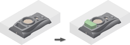
To create or work with an Insert
Create an insert by using a shape
Use a Profile.
In the Core/Cavity tab, click Create Insert.
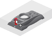
In the graphics window, select the faces on which to model the insert.
Note: Select only faces on the product, core, cavity, inserts, and core pins.In the dialog box, click Profile Loops.
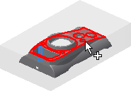
In the graphics window, select the profile loops used to loft the insert.
Note: Select only faces on the product, core, cavity, inserts, and core pins.In the Termination group, define the length of the insert by using one of the following methods:
Molding
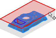
In the graphics window, select a plane.
Distance
In the graphics window, select a plane or edge, and then enter a Distance value. If necessary, click Direction to reverse the direction of the insert.
Expand the Insert dialog box to set the following additional parameters:
Offset Insert
Enter the distance between the insert start plane and the insert sketch plane.
Taper
Enter the draft angle of the extension insert.
Select Clearance to enable the Clearance tab, in which you can specify clearance dimensions.
Click OK.
Use the Face Set Tool.
In the Core/Cavity tab, click Create Insert.
To create the profile loops without manually selecting edges, check the option Automatic profile loops. The boundary faces must be adjacent to each other to generate the loops.
Click the Select seed face selection arrow.
Select a seed face in the graphics window.
 Tip: Enable Automatic profile loops before selecting the seed face to generate the loops for adjacent faces automatically.
Click the Select boundary faces selection arrow.
Select a boundary face in the graphics window.
In the dialog box, click Generate/update the selection set.
Click Add the selection set into Faces selection to generate the geometry.
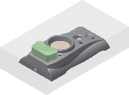
In the Termination pane, click the Molding or Distance option. The following image uses the Molding option.
In the graphics window, click the termination plane.
Click OK to create the insert.
Create an insert by using a template
In the Core/Cavity tab, click Create Insert.
In the Insert dialog box, select the Template method, and then select a template from the following types:
- Rectangle
- Square
- Circle
- Key1-Flat
- Key2-Flats
- Slot
- Rounded Rectangle
In the Placement group, select a type of placement:
Option Description Linear In the graphics window, select a plane on which the sketch template lies, and two reference edges to locate the template. Concentric In the graphics window, select a plane on which the sketch template lies, and a circle, arc edge, or cylinder face to locate the template. UV values In the graphics window, select a plane on which the sketch template lies.
In the Termination group, define the length of the insert by using one of the following methods:
Molding
In the graphics window, select the reference surfaces or the component to be the end face of the insert.
Distance
In the graphics window, select the reference component to trim the insert solid.
To rotate the sketch template, enter a rotation angle.
Expand the Insert dialog box to set the following additional parameters:
Offset
Enter the distance between the insert start plane and the insert sketch plane.
Taper
Enter the draft angle of the extension insert.
On the Clearance tab, specify clearance dimensions.
Click OK.
Create an insert from a sketch
On the Core/Cavity tab, click Create Insert.
In the Insert dialog box, select the From Sketch method.
Note: This method displays in the list only if an Insert Sketch exists.In the graphics window, select an insert sketch to extrude.
In the Termination group, define the length of the insert by using one of the following methods:
Molding
In the graphics window, select the reference surfaces or the component for the end face of the insert.
Distance
In the graphics window, select the reference component to trim the insert solid.
Expand the Insert dialog box to set the following additional parameters:
Offset
Enter the distance between the insert start plane and the insert sketch plane.
Taper
Enter the draft angle of the extension insert.
On the Clearance tab, specify clearance dimensions.
Click OK.
Edit an insert
- In the Mold Design browser, under Inserts, right-click an Insert node, and then click Edit Feature.
- In the Insert dialog box, modify the parameters.
- Click OK.
Delete an insert
- In the Mold Design browser, under Inserts, right-click an Insert node, and then click Delete.
Add a trim participant for an insert
- In the Mold Design browser, under Inserts, right-click an Insert node, and then click Add Participant.
- In the graphics window, select an insert or a core pin. The insert relating to the Insert node trims the selected insert or core pin immediately.
Remove a trim participant for an insert
- In the Mold Design browser, under Inserts, right-click a Trim Participant node of an Insert node, and then click Remove Participant.