To Create Model States
Create table driven designs with unique parameter values and properties.
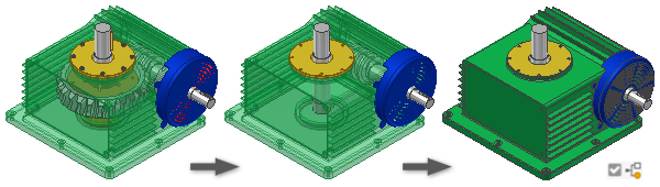
Use Model States in part and assembly files to represent your designs at multiple states, simplification levels, and sizes in one file.
The first model state entry in both parts and assemblies is named Primary. Primary can be modified as desired like other model states, but Primary cannot be renamed, reordered, or deleted.
The iProperties of the Primary model state are exposed to other programs.
At any time, you can change to a different model state. Double-click its name in the browser to activate it, or if you prefer, right-click the name and select Activate.
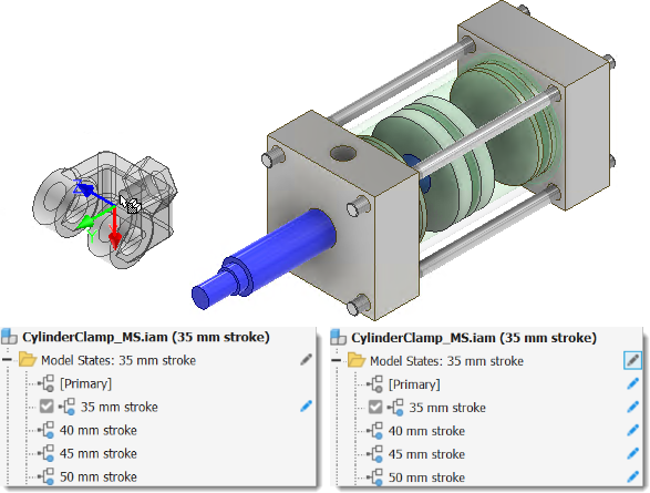
When you create model states, it is important to be aware of the edit scope status. If Edit Member Scope is enabled, changes, including changes to iProperties, are applied only to the active member. If Edit Factory Scope is enabled, changes, including changes to iProperties, are applied to all members.
You can toggle between Edit Member Scope and Edit Factory Scope in the browser by clicking Toggle Edit Scope in the browser (pencil icon) at top of the Model States entry.
In the following image, the Edit Member Scope state is active in the left browser. The clevis is added only to the 35 mm stroke model state. In the browser on the right, Edit Factory Scope is active and the clevis is added to all members.
Create a part Model State
You can use part model states to capture manufacturing processes, create simplified versions of a part, or create families of parts.
Create a part file that contains the common features of the model.
In the browser, right-click the Model States folder and click New.
The active model state is copied.
Assign a unique name to the model state.
Toggle the edit scope to the proper setting and continue to add, modify, and suppress features as desired.
Optionally, edit the iProperties to assign unique attributes.
To add a model state, do one of the following:
- Right-click the Model States folder and select New. `- Right-click an existing model state and select Copy.
Assign a unique name to each model state.
Add, suppress, or modify features as desired.
Optionally, edit the iProperties to assign unique attributes.
Double-click a model state in the browser to make it active.
Save the file.
Create an assembly Model State
You can use assembly model states to capture manufacturing processes, assembly level features, create simplified versions of an assembly, and create families of components.

Create an assembly file that contains the common components of the model.
In the browser, right-click the Model States folder and click New.
The active model state is copied.
Assign a unique name to the model state.
Toggle Edit Scope to the proper setting and continue to add, modify, and suppress features as desired.
Optionally, edit the iProperties to assign unique attributes.
Do one of the following to add a model state:
- Right-click the Model States folder and select New.
- Right-click an existing model state and select Copy.
Assign a unique name to each model state.
Add, suppress, or modify features and components as desired.
Optionally, edit the iProperties to assign unique attributes.
Double-click a model state in the browser to make it active.
Save the file.
Create a Substitute Model State using Derive
Expand the Model States folder and right-click Substitutes. Expand New Substitute and click Derive Assembly.
In the New Derived Substitute Part dialog box, name the component, select a template to use if appropriate, and assign the new file location. Click OK to continue.
On the Bodies tab, select Derive style and Status.
Select the Other tab and set the required include or exclude status.
Select the Representations tab and set the Model State, Design View, and Position View.
Select the Options tab and set the desired Simplification, Visibility, Hole patching, and other settings.
Note: Reduced Memory Mode is on by default. A derived part created using this mode uses less memory by not caching any source bodies. We recommend that you leave this option on.Click OK to create the derived part, mark the new part as a substitute, close the window and return to the owning (source) assembly.
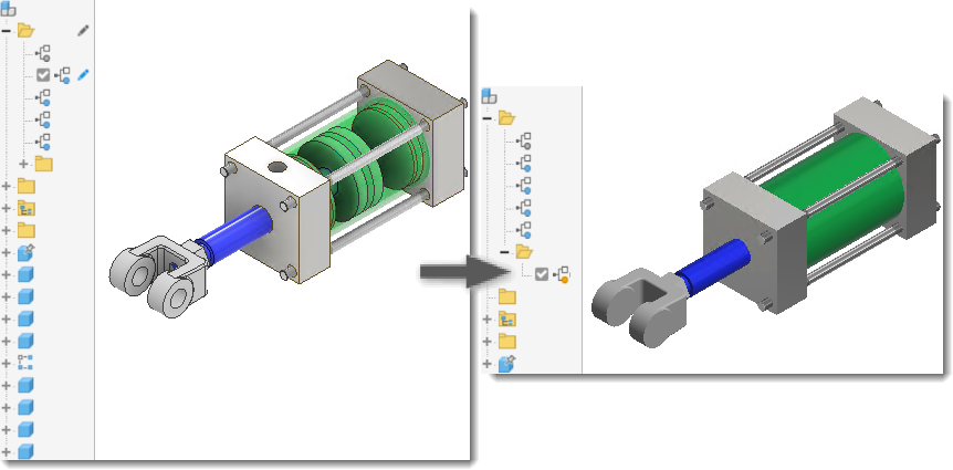
Create a Substitute Model State using Simplify
- (Optional) Calculate the Mass Properties of the assembly to include them in the substitute.
- (Optional) Create a Design View representation that contains only the required components.
- (Optional) Activate the representation.
- Expand the Model States folder and right-click Substitutes. Expand New Substitute and click Simplify.
For information on how to use the Simplify command, see Create a Simplified Part from an Assembly.
Create a Substitute Model State using a part file on disk
- Create a simplified representation of the assembly by modeling a part or by creating a derived part from an assembly. Save the file to disk.
- In Model States browser of the assembly file, right-click Substitutes, select New Substitute, and then Select Part File.
- In the Place Component dialog box, select the simplified part file to use as the substitute, and then click Open.
- The Model States Substitutes browser node displays the Substitute icon
 and the name Substitute1. As with other browser entries, you can rename the Substitute entry.
For more information about using Model States with Vault, see Working with Model States and Vault Files.