To Mark Faces
What's New: 2023, 2023.1, 2023.2, 2024
Use the Mark command to add laser marking, etching, and engraving features to faces.
If you are using custom styles created prior to R2023, the Mark style file mark.xml must exist in the Design Data folder in order to use the Mark command. An error is displayed if the Mark style does not exist. You can copy the file from the installed Design Data folder to the current Design Data folder.
The Mark sketch geometry must be located completely within the boundary face and outside of the model volume.
Note: The Mark command is not available for multi-body parts.
Create a Mark feature
This workflow describes the Mark feature use on a sheet metal part. Mark features are not limited to sheet metal parts and the workflow is the same except for specific sheet metal references.
Click Sheet Metal tab or 3D Model tab
 Modify panel Mark
  .
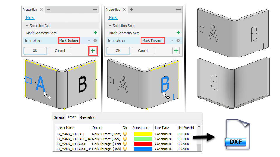
.- Select Mark Surface to apply the mark to a single face and to outline the text.
- Select Mark Through to apply the mark to multiple faces and to convert text characters to a single stroke path based on the selected font.
Select the sketch text or geometry. If no sketch exists, you are prompted to select the face where the mark is to be placed, then, a sketch is activated on that face.
Optionally, click Add Mark set
 and continue to select text or sketch geometry. You can set Mark Surface or Through for each member.
Specify the feature Behavior, choosing either Project or Wrap.
 Projects the sketch geometry to a face. Select this method and the desired direction option.
 Wraps the sketch geometry to a cylindrical face. Select this method and the target face.
Click Apply
 to continue to use the Mark command or click OK to finish.
Mark features defined in a flat pattern are not included in the folded model or drawing views of the folded model.
You cannot pattern or mirror a Mark feature.
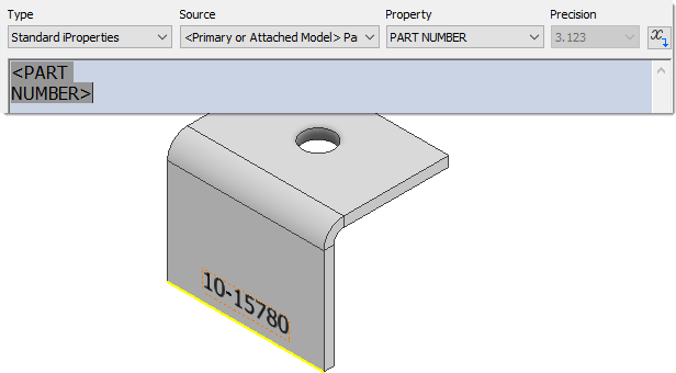
You can use iProperty values in sketch text to create Mark features that are associative to the iProperty value.
Open the Styles Editor to add or edit the Mark styles. You can set the mark surface or through options, text options, and other DXF/DWG layer export properties in styles.
For more information, see Style and Standard Editor - Mark Style Reference.
Edit a Mark feature
- Right-click a Mark feature in the browser and select Edit Feature in the context menu.
- Make the necessary changes. If the change requires editing the sketch, you can do that from the Mark property panel breadcrumb, click Sketch and the sketch is activated in edit mode.
- Click OK to finish.
Export Mark feature layer information
To export a Mark feature with DXF/DWG layer information:
- Create a sheet metal part with one or more Mark features in the folded model or the flat pattern.
- Create a flat pattern.
- Right-click the Flat Pattern in the browser and select Save Copy As in the context menu.
- Enter a File name and choose DXF or DWG in the Save as type value field.
- Click Save.
- In the Flat Pattern DXF/DWG Export Options dialog, click the Layer tab.
- Scroll to the Mark feature layer names and make any desired changes.
- Click OK to finish.