To Apply Geometric Constraints
Apply Constraints Automatically
In a 2D sketch, geometric constraints are inferred and applied automatically as you sketch. Hold the Ctrl key down to temporarily disable applying constraints. In a 3D sketch, enable Infer Constraints in the status bar to automatically apply constraints as you sketch. Use Ctrl + I to toggle Infer Constraints on and off.
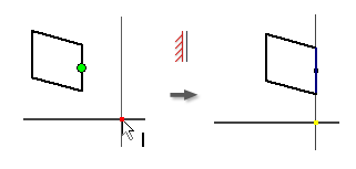
Apply a Coincident Constraint
The Coincident constraint causes two points to be constrained together, or causes one point to lie on a curve. In a 3D sketch, a coincident constraint can also cause points and lines to be constrained to surfaces.
The yellow coincident dot represents the presence of the constraint. To identify the geometry affected by the constraint, hover over the yellow dot. The coincident constraint glyphs appear. Pause the cursor over a glyph to show the affected geometry .
The green coincident dot means the coincident constraints are enabled to remove in relax dragging in Relax Mode.
In an active sketch, click Sketch tab
 Constrain panel Coincident Constraint
  (2D)or3D Sketch tab Constrain panel Coincident Constraint (3D sketch).
In the graphics window, click to set the point to constrain.
Click the geometry to which the point is constrained.
Right-click and choose Done, press Esc, or select another tool or command.
When applying coincident constraints, keep in mind:
- A coincident constraint is automatically created on the endpoints of curves created in succession with the Line command.
- A point constrained to a curve can lie outside the extents of the curve.
- A point coincident with a curve slides along the curve so that the point can lie anywhere along the curve, unless other constraint or dimensions prevent the point from moving.
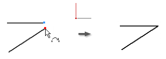
Apply a Collinear Constraint
- In an active sketch, click Sketch tab Constrain panel Collinear Constraint
 (2D) or click 3D Sketch tab Constrain panel Collinear Constraint (3D sketch).
 - Click the first line in a 2D or 3D sketch or an ellipse axis in a 2D sketch.
- Click a second line in the same 2D or 3D sketch or an ellipse axis in the same 2D sketch.
- Right-click and choose Done, press Esc, or select another tool or command.
Apply an On Face Constraint
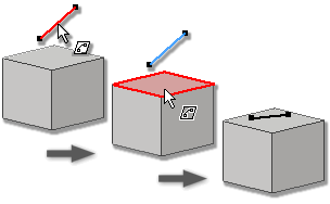
- In an active 3D sketch, click 3D Sketch tab Constrain panel On Face Constraint
 .
. - In the graphics window, click the first point, line, arc, or spline.
- Click the planar destination face for a point, line, arc or spline, or select a curved face for a point.
- Right-click and choose Done, press Esc, or select another tool or command.
Apply a Concentric Constraint (2D Sketches)
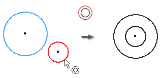
The Concentric constraint causes two arcs, circles, or ellipses to have the same center point.
- In an active sketch, click Sketch tab Constrain panel Concentric Constraint
 .
. - In the graphics window, click the first arc, circle, or ellipse.
- Click the second curve to be concentric to the first.
- Right-click and choose Done, press Esc, or select another tool or command.
Apply a Fix Constraint
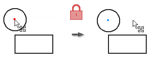
The Fix constraint fixes points and curves in position relative to the sketch coordinate system. If you move or rotate the sketch coordinate system, fixed curves or points move with it.
On the ribbon, click Sketch tab
Constrain panel Fix  (2D) or click 3D Sketch tab Constrain panel Fix (3D sketch).
In the graphics window, click a curve, center point, midpoint, or point.
Click curves or points to fix, as desired.
Right-click and choose Done, press Esc, or select another tool or command.
When you apply a Fix constraint:
- Lines are fixed in position and angle but endpoints can move to shorten or lengthen the line.
- Circles and arcs have fixed center point and radius.
- Arc and line endpoints are free to move along the extents of the radius or length.
- Fixed endpoints or midpoints allow rotation of lines or arcs about the points.
- Position, size, and orientation of a circle or ellipse are fixed.
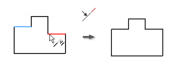
Apply a Parallel or Perpendicular Constraint
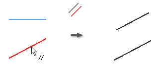
The Parallel constraint causes selected lines or ellipse axes to lie parallel to one another. In a 3D sketch, Parallel is available for sketch geometry, axes, planes, spline handles or to selected model geometry.
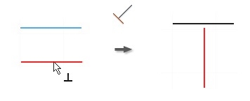
The Perpendicular constraint causes selected lines, curves, or ellipse axes to lie at 90 degrees to one another.
In an active sketch, click any of the following:
- Sketch tab Constrain panel Parallel Constraint
 (2D sketch)
 - 3D Sketch tab Constrain panel Parallel Constraint (3D sketch)
- Sketch tab Constrain panel Parallel Constraint
 (2D sketch)
 - 3D Sketch tab Constrain panel Parallel Constraint (3D sketch)
- Sketch tab
In the graphics window, click the first line, curve, or ellipse axis.
Click a second line, curve, or ellipse axis.
Right-click and choose Done, press Esc, or select another tool or command.
Note: To add a perpendicular constraint to a spline, the constraint must be applied endpoint to endpoint between the spline and the other curve.
Apply a Parallel X, Y, or Z Constraint (3D Sketches)
Causes the selected geometry to lie parallel to the origin x, y, or z axis.
- In an active 3D sketch, click any of the following:
- 3D Sketch tab Constrain panel Parallel with X Axis

- 3D Sketch tab Constrain panel Parallel with Y Axis

- 3D Sketch tab Constrain panel Parallel with Z Axis

- 3D Sketch tab
- In the graphics window, click a line, curve, or spline handle. The selected constraint is applied.
- Optionally, select more lines, curves, or spline handles to constrain.
- Right-click and choose OK, or press Esc to finish.
Apply a Parallel with XY, YZ, or XZ Plane Constraint (3D Sketches)
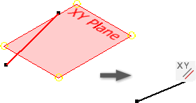
Causes the selected geometry to lie parallel to the origin xy, yz, or xz plane.
- In an active 3D sketch, click any of the following:
- 3D Sketch tab Constrain panel Parallel with XY Plane

- 3D Sketch tab Constrain panel Parallel with YZ Plane

- 3D Sketch tab Constrain panel Parallel with XZ Plane

- 3D Sketch tab
- In the graphics window, click a line, curve, or spline. The selected constraint is applied.
- Optionally, select more lines, curves, or splines to constrain.
- Right-click and choose OK, or press Esc to finish.
Apply a Horizontal or Vertical Constraint (2D Sketches)
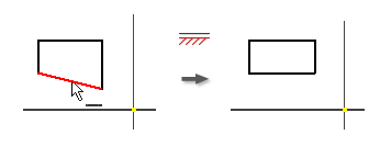

The Horizontal constraint causes lines, ellipse axes, or pairs of points to lie parallel to the X axis of the coordinate system.
The Vertical constraint causes lines, ellipse axes, or pairs of points to lie parallel to the Y axis of the coordinate system.
- On the ribbon, click Sketch tab Constrain panel Horizontal Constraint or Sketch tab Constrain panel Vertical Constraint
 .
. - In the graphics window, click a line, an ellipse axis, or two points.
- Click more lines, ellipse axes, or pairs of points as desired.
- Right-click and choose Done, press Esc, or select another tool or command.
Apply an Equal Constraint
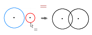
- In an active sketch, click Sketch tab Constrain panel Equal
 (2D sketch) or click 3D Sketch tab Constrain panel Equal (3D sketch).
 - In the graphics window, click the first circle, arc, or line.
- Click a second curve of the same type to make them of equal size.
- Right-click and choose Done, press Esc, or select another tool or command.
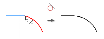
Apply a Smooth (G2) Constraint (2D Sketches)
The Smooth (G2) constraint causes a continuous curvature (G2) condition between a spline and another curve, such as a line, arc, or spline.
- In an active sketch, click Sketch tab Constrain panel Smooth (G2)
 (2D sketch) or click 3D Sketch tab Constrain panel Smooth (G2) (3D sketch).
 - In the graphics window, click the spline and the curve attached to the spline endpoint to add the Smooth constraint. The spline curvature adjusts as required to create a G2 condition.
- Right-click and choose Done, press Esc, or select another tool or command.
Apply a Symmetric Constraint (2D Sketches)
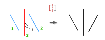
The Symmetric constraint causes selected lines or curves to become proportionately constrained about a selected line. Segments constrained to the selected geometry reorient when the constraint is applied.
In an active sketch click Sketch tab
Constrain panel Symmetric  .
.In the graphics window, click the first line or curve.
Click the second line or curve.
Click the line of symmetry.
Right-click and choose Done, press Esc, or select another tool or command.
When applying symmetric constraints, keep in mind:
- If you delete the line of symmetry, the symmetric constraints are also deleted.
- Selected lines and arcs are constrained about a line to create a symmetrical shape. All geometry constrained to the selected shapes also moves when the constraint is applied.
- The symmetry line can be of any line type.
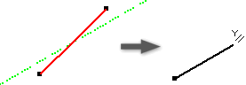
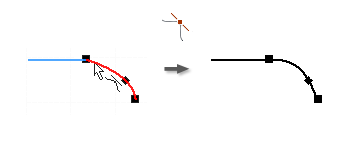
Apply a Tangent Constraint
In an active sketch, click Sketch tab
Constrain panel Tangent  (2D sketch) or click 3D Sketch tab Constrain panel Tangent (3D sketch).
In the graphics window, click the first curve.
Note: In 3D sketches, the first selected curve must be a spline. Subsequent selections can be any geometry in the sketch, including a model edge, that shares an endpoint with the spline.Click the second curve.
Right-click and choose Done, press Esc, or select another tool or command.