To Rip Sheet Metal Features
Some sheet metal designs (for example, transitional shapes created with Lofted Flange) created from closed profile sketches require a rip to flatten them.
A cut feature can also create such a gap, but the Rip feature has edges normal to the cut surface, and several options to simplify feature creation.
You can create rips in three ways:
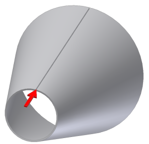
A Single Point rip uses a single point on the edge of a surface. The selected point can be a midpoint on an edge, an endpoint on a face vertex, a work point, or a sketched point from a previously created sketch.
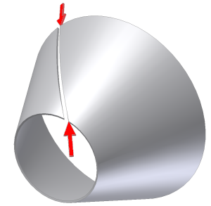
A Point-to-Point rip uses points on opposite sides of the face to define the Rip begin and end. The two points can be work points, midpoints on face edges, endpoints on face vertices, or sketch points from a previously created sketch.
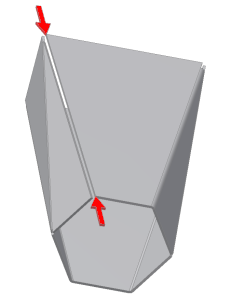
A Face Extents rip removes any entire selected face (typically a bend face). You can also use a Face Extents Rip feature to remove a small bend face created as the result of a Lofted Flange created using Press Brake output.
You can place a Rip feature anywhere within the feature history. A single sheet metal model can contain multiple Rip features.
The labels that appear in the Rip dialog box depend on which type of rip you specify.
- On the ribbon, click Sheet Metal tab
 Modify panel Rip
  .
. - In the Rip dialog box, Rip Type drop-down list, specify how to create the rip.
- Single Point. Creates a rip from a single selected point.
- Point to Point. Creates a rip from a selected start and end point.
- Face Extents. Removes the selected face to define a rip.
- Use Rip Face to select the face of the sheet metal model to rip.
- For single point or point-to-point rip, do one of the following:
- For a single-point rip, use Rip Point and then select the point that defines the rip location.
- For a point-to-point rip, use Start Point to select the begin point and then use End Point to specify the end point for the rip.
- (Optional) For a single point rip or point-to point rip, in Rip Gap Value, enter a value that differs from GapSize.
- (Optional) For a single point rip or point-to point rip, specify whether to locate the Rip gap on the selected point, or offset to the right or left.
- Flip Side
 or
or  . Offsets the Rip gap to the opposite side of the selected point.
 - Both Sides
 . Offsets the Rip gap to both sides of the selected point.
- Flip Side