Configurations and Representations
Use configurations to maintain a common set or series of designs. Use representations to control the view and positional aspects of the design.
Configurations
Use iParts, and iAssemblies to manage product configurations. Use Model States to manage manufacturing stages and assembly level features or a set of designs.
- Use iFeatures to create families of commonly used features.
- Use iParts and iAssemblies to create families of products controlled by a primary model. Each member has their own properties and part number and is stored in a separate file that can be managed and released. iAssemblies use Exclude to remove members.
- Use Model States to capture manufacturing stages, assembly level features, simplified versions, or a set of designs in a single file. Each member can have their own part number, BOM, and other properties. Model States use Suppress to remove members. Suppressed members do not participate in the BOM or consume memory. You can also use Model States to create a substitute representation of an assembly to reduce overhead or protect intellectual property.
Edit Scope
The following settings determine how Model States, iParts and iAssemblies react to edits. All members respond to edits when Edit Factory Scope is enabled. Only the active member responds to edits when Edit Member Scope is enabled. To change the scope settings:
On the ribbon, click Manage tab
 Author panel Edit Factory Scope
  .
.When you enable Edit Factory Scope, features or components added to the active member are added to all members. Table columns are not added in this mode.
On the ribbon, click Manage tab
Author panel Edit Member Scope  .
.When you enable Edit Member Scope, features or components added to the active member are not added to all members. Table columns are added and removed in this mode.
To remove members from participation:
- Use Suppress in the table for Models States
- Use Exclude in the table for iAssemblies
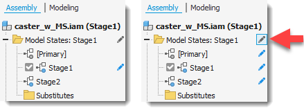
You can also change the scope settings in the browser. Click Toggle Edit Scope to toggle between Edit Member Scope and Edit Factory Scope.
Edit Member Scope applies edits to the active member. Edit Factory Scope applies edits to all members. In the following image, Edit Member Scope is enabled on the left, and Edit Factory Scope is enabled on the right.
Representations
Use representations to maintain a group of saved states and attributes for a document.
- Use View representations to save display configurations that you can recall by name when you work on the component. Views control component visibility, color, and other view related properties.
- Use Positional representations to configure an assembly in different positions and states.
How do I know which one to use?
The following chart contains a description of the usage and areas of impact for the configurations and representations. Use this information to determine the appropriate type and combination to use.
| Tool |  Model States Model States | |||
| Purpose | Visibility state, color overrides, camera position, section view, sketch, dimension, annotation, and work feature visibility | Display assemblies in different physical positions or states | Create table driven parts and assemblies in a single file. | Primary model generates table driven parts and assemblies. Each member is stored in a separate file that can be managed and released. |
| Separate files | No | No | No | Yes |
| Used to manage | Visibility and other view attributes | Constraint value, grounding status, positional offset values | Feature and component suppression, assembly simplification (substitutes) | Component exclusion, part feature suppression (and other configuration properties) |
| Effect on graphics window | Multiple | Modifies position of assembly components | Model display changes to reflect active member | Model display changes to reflect active table row |
| Effect on assembly BOM and drawing manager parts list | Yes (parts list can be filtered to show only design view members) | No | Yes Suppressed components do not participate in the BOM or Parts List | Yes Excluded components do not participate in the BOM or Parts List |
| Drawing manager command access | Base View, Edit View | Base View, Edit View (for Base View only) | Base View, Edit View (view can display any of the defined configurations) | Base View, Edit View (view can display any of the defined configurations) |
| Usage in drawing manager | Creating custom, or specialty views without reorganizing the assembly. Speed up view generation, filter the parts list to show only design view members | Showing assemblies in different positions | Documenting manufacturing stages, assembly features, or a set of designs | Documenting product families and variants |