To Work with Lock Sets
Create a side lock
Position the side lock
In general, the male lock attaches to the bottom face of the top plate. The female lock attaches to the top face of the bottom plate. To attach a side lock, first define the base face, the reference face, the distance, and the offset.
- Base face The top or bottom surface of the mold base plates, which establishes the location of the parting plane.
- Reference face The face to which the side lock is attached.
- Distance The measurement between the center of the reference face and the center of the side lock.
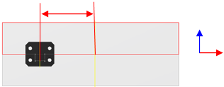
- Offset the distance into the mold plate that the side lock is embedded. Negative values mean that the side lock is external to the mold base plates, and positive values indicate that the side lock is embedded.
In the Mold Assembly tab, click Lock Set.
In the Lock Set dialog box, select the type of interlock in the Type drop-down box.
Note: In the selection box, choose Side Lock in the Category drop-down list.In the table next to the image, modify the parameters.
Click Base face and then in the graphics window, select the top or bottom face of the plates to align.
Click Reference face and then in the graphics window, select a face perpendicular to the base face.
In the Lock Set dialog box, in Placement, enter values to position the component:
- The first value adjusts the position of the side lock relative to the center of the reference face.
- The second value adjusts the offset from the reference face.
To place a symmetrical side lock, select Symmetrical Placement.
Click OK or Apply.
Create an interlock
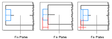
Position the interlock
In general, the male lock attaches to the bottom face of the top target plate. The female lock attaches to the top face of the bottom target plate. Before you attach an interlock, determine the base face, Reference 1, Reference 2, and whether you want to rotate the interlock.
- Base face the top or bottom surface of the mold base plates, or the face of the core and cavity. Establishes the location of the parting plane.
- Reference 1 the first of the two edges on the face that is closest to the location of the interlock.
- Reference 2 the second of the two edges on the face that is closest to the location of the interlock.
- Rotate the degree to which to rotate the interlock. Available only for the taper bar interlock.
On the Mold Assembly tab, click Lock Set.
In the Lock Set dialog box, select the type of interlock in the Type drop-down box.
Note: In the selection box, in the Category drop-down list, click Interlock .Click Lock Mold Base or Lock Core and Cavity to specify whether to use the interlock to align the mold plates or the core and cavity.
In the table next to the component image, modify the parameters.
Click Base face and then in the graphics window, select the top or bottom face of the plates to align.
Click Reference 1 and then in the graphics window, select an edge of the base face.
Click Reference 2 and then in the graphics window, select a second edge of the base face, perpendicular to the first reference edge.
To position the component in the graphics , click dimension line, and then enter a value in the Edit box.
For a taper bar interlock, click Rotate to define the rotation of the interlock.
To place a symmetrical interlock, select Symmetrical Placement.
Click OK or Apply.
Edit a lock set
- In the Mold Design browser, under Lock Sets, right-click a Side Lock node or an Interlock node, and then click Edit Feature.
- In the Lock Set dialog box, modify the parameters.
- Click OK.
Delete a lock set
- In the Mold Design browser, under Lock Sets, right-click a Side Lock node or an Interlock node, and then click Delete.