To Work with Cuts on Sheet Metal
You can specify normal cuts or cuts across a bend. You can also project unfolded geometry in your sketch.
What's New: 2025
For convenience, you can also project the unfolded geometry in your sketch.
Unfold Sketch Geometry for Cut Feature
When creating a profile sketch to use for a cut feature that cuts across bends, it is useful to have unfolded geometry projected in your sketch. This command projects the flattened face along with bend lines, which you can use to dimension your sketch.
- Select a planar face to start your sketch.
- Use Project Flat Pattern (located with the Project Geometry and Project Cut Edges commands) to select faces next to your originally selected sketch face.
- Use the sketch Slice Graphics option to remove folded model geometry from the plane of your sketch.
Apply Cuts Across Bends
On the ribbon, click Sheet Metal tab
 Modify panel Cut
  .
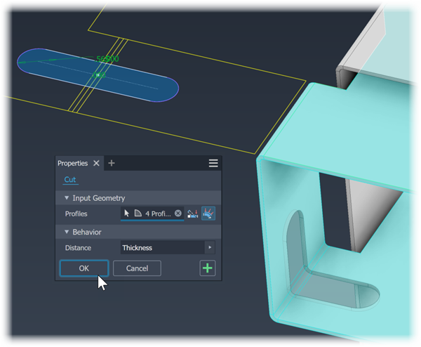
.In the property panel, for Input Geometry, the Profile selector is active and if there is only one profile it is automatically selected.
- If there are multiple profiles, click the Profiles selector, if it isn't active, and then select one or more profiles for the cut.
- If there are multiple bodies in the part file, click the Solids selector to choose the participating body.
Next to the Profiles selector, click
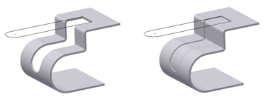
 Cut Across Bend. The cut feature extrudes to the specified distance, Thickness is the default, and wraps across bends normal to the affected faces while maintaining the sketch geometry parameters. In the Flat Pattern, the cut matches the sketch profile.
Click OK or
 Apply if additional cut features are needed and the profiles are ready.
Apply Cuts Normal to the Sketch Face
On the ribbon, click Sheet Metal tab
Modify panel Cut .In the property panel, for Input Geometry, the Profile selector is active and if there is only one profile it is automatically selected.
- If there are multiple profiles, click the Profiles selector, if it isn't active, and then select one or more profiles for the cut.
- If there are multiple bodies in the part file, click the Solids selector to choose the participating body.
Next to the Profiles selector, click
 Cut Normal.
Under Behavior, choose the options needed to create the desired cut feature:
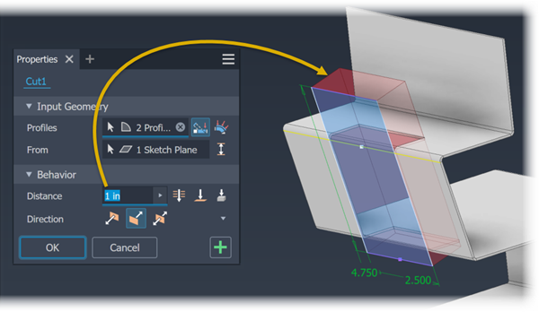
Distance. Establishes the depth of the cut. The default method creates a cut perpendicular to the sketch plane. To the right of the Distance field, click the method you want to use to define the distance. The cut feature result previews in red.
Specify a distance for the cut feature.
 Through All: Extrudes the cut profile through all features and sketches in the specified direction.
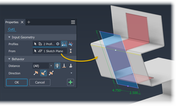
 To: Extrudes the cut profile to the selected face or work plane. (You can terminate the cut on a face that extends beyond the termination plane.) In an assembly, the face or plane can be on another part. Specify whether the cut extends beyond the selected face.
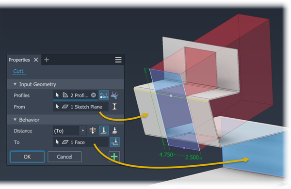
 To Next: Selects the next possible face or plane on which to terminate the extrusion in the specified direction. Use this selector to pick a solid or surface on which to terminate the cut and determine the direction.
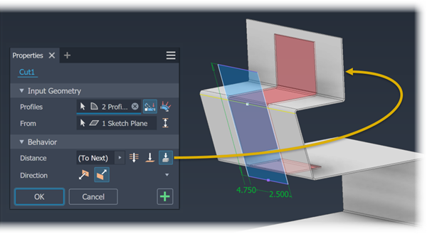
Other ways of specifying the distance are accessed from the selector flyout and include:
- Measure. Uses the distance defined by two points or an edge for the thickness of the cut.
- Select Feature Dimension. Displays the dimensions for a selected feature. Uses the distance determined by a selected dimension as the thickness for the cut.
- List Parameters. Displays a list of the defined parameters in the file. You can select one as the thickness for the cut.
The Sketch plane specifies the direction. There are options to the sketch plane direction, these are:
 . Flips the direction of the cut from the default setting. Useful when the cut sketch is created on a reference plane. When the sketch is created on a sheet metal face, results in no material removal.
 . Removes material from the plane of the selected sketch towards the material thickness of the part. Default direction.
 . Defines the cut sketch as the midplane of the cut thickness. Useful when the cut sketch is created on an appropriately positioned reference plane.Tip: If the cut feature doesn't preview, try selecting a different direction option.
To Cut Between Two Faces
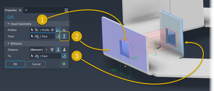
Click Profiles selector, if not already active, and then select one or more profiles.
To the right of the From selector, click
 Between and select the starting face for the cut feature. The Distance parameter updates to show Between is selected.Note: If the From face is not directly in line with the cut profile, the option Extend face to start feature is turned on.
If not active, click the To selector and then select the face at which the cut feature will end.
Note: If the To face is not directly in line with the cut profile, the option Extend face to end feature is turned on.Click OK to create the cut feature.