To Work with Bend Features on Sheet Metal
You can add, edit, and delete bends.
Bend features can join sheet metal faces that do not touch. When you select edges on sheet metal features, you add material to the model using the bend radius and material thickness defined by the sheet metal style.
Faces extend in compliance with your default (or selected) bend radius. If the faces are parallel, but not coplanar, you can add a double bend. Depending on the distance between the faces, the bends are trimmed so that they are tangent, or a face is created between the two bends.
A single flange or contour flange feature in a sheet metal part can contain any number of bends.
You can override default sheet metal styles from the Bend dialog box as you create your sheet metal bend. These settings include how the flat pattern unfolds, and the bend relief settings between faces.
Add a Bend to a Sheet Metal Face
On the ribbon, click Sheet Metal tab
 Create panel Bend
  .
.Select a model edge on each sheet metal face.
Optionally, on the Shape tab, specify one of the following to extend the bend:
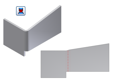
- Extend Bend Aligned to Side Face. Extends material along the faces on the side of the edges connected by the bend instead of perpendicularly to the bend axis. Useful when side edges of face are not perpendicular. In the following images, the same bend is created using each option. The first image shows the bend extension aligned to the side face. Compare the area of the flat pattern on either side of the bend zone.
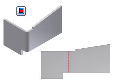
- Extend Bend Perpendicular to Side Face. Extends material perpendicularly to the side face (default), as shown in the following image. Note the area of the flat pattern on either side of the bend zone, and compare with the same area on the flat pattern shown previously.
Accept the default bend radius specified in the active sheet metal style, or on the drop-down list, click Measure, Show Dimensions, or List Parameters to enter a different value.
Add a double bend to a sheet metal face
On the ribbon, click Sheet Metal tab
Create panel Bend .Select a model edge on each sheet metal face.
Enter a Bend Radius if it is different from the default for the part.
Click the down arrow to select Measure, Show Dimensions, or List Parameters to enter a different value.
If the faces are parallel but not coplanar, select one of the following Double Bend options:
- Fix Edges
- 45 Degree
- Full Radius
- 90 Degree
- Flip Fixed Edge
Click Apply to continue to add bends or click OK to close the dialog box.
Edit Bends in Sheet Metal Parts
Click the Bend Edit glyph for your selected bend.
In the Bend Edit dialog box’s drop-down list for Type, click Width Extents, and modify the width extent parameters as required by width type you select:
- Edge. Resets an entire edge that was previously defined with Width, Offset, or From/To.
- Width. Click either Centered or Offset, and enter a value. Centered, which is the default enters the width on the selected edge. Offset offsets the specified width from a selected face (vertex, work plane, or work point) to define Offset 1 and Offset 2. You can enter a value or flip offset to opposite side of the selection.
- From/To. Select from face or to face (vertex, work plane, or work point).
Reset All Bends in a Sheet Metal Feature to Defaults
- In the browser, under a feature which contains modified bends, right-click the bend node, and click Reset All Bends.