To Work with Corners in Sheet Metal Feature
You can edit sheet metal corners, override their default Style settings, and apply auto-mitering.
You can also override default parameters, apply auto-mitering, and specify 2- or 3-bend corners.
Edit Corners in Sheet Metal Features
The Corner Edit dialog box lets you can specify an overlap type, overlap gap, relief type, and relief size that differ from your sheet metal style or from the default value specified in the active sheet metal style.
- Click the Corner Edit glyph for your selected corner.
- Specify any of the following in the Corner Edit dialog box:
- To specify an overlap that differs from the value specified, select Overlap Type in the Corner Edit dialog box.
- To specify an overlap gap, select Overlap Gap. (You can also use the Real Value edit drop-down list on this field.)
- To specify a percentage of overlap with either the Overlap or Reverse Overlap type, enter a value from 0 to 1 for Overlap Gap.
- To specify a corner relief, select from the Relief Type drop-down list. (The selections available for a two-bend corner differ from the selections available for a three-bend corner.)
- To specify a relief size, select Relief Size and specify a value. You can also use the options on the Real Value edit drop-down list.
Return Corners to Defaults Specified by the Sheet Metal Feature
- In the browser, under a feature that contains modified corners, right-click the corner node, and click Reset All Corners.
Override Sheet Metal Style Settings for Corner Shape and Relief
The Corner tab lets you override default parameters in the Sheet Metal Styles dialog box. You can specify the corner relief shape for a 2 or 3 bend corner. You can also specify the relief size, and whether to apply auto-mitering. (Not all options described are available or valid for each feature that shares this tab.)
In the Contour Flange, Flange, or Corner Seam dialog box, click the Corner tab.
To define the Default corner relief shape when two bends intersect, select one of the following from the Relief Shape drop-down list:
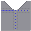
Round. A circular cut out centered on the intersection of the bend lines.
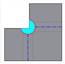
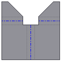
Square. A square cut out centered on the intersection of the bend lines.
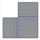
Tear. Extends the flange edges to their intersection. No relief, which allows material failure (tearing) across the bend zone in the folded model.
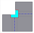
Trim to Bend. A polygonal cut out bounded by the bending zone lines.

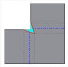
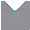
Linear Weld. A v-shaped cut out defined from the intersection of the inner bend zone lines to the outer bend zone intersection of the line with the flange edges. Minimum relief allows a subsequent weld operation to close the corner.
Arc Weld. Curves tangent to the flange edges along the outside edge of the bend zone which converge to a flat gap equal to the Miter Gap value. A gap between the flanges that is equidistant along the length of the relief is suitable for subsequent arc welding.
Laser Weld. Curves tangent to the flange edges along the outside edge of the bend zone which converge to a tangent arc equal to the Miter Gap value. A gap between the flanges that is equidistant along the length of the relief is suitable for subsequent laser welding.
To define the Default corner relief to display in the flat pattern when three bends intersect, select one of the following. (The folded model does not display the selected relief option.)
No Replacement. Does not replace the geometry as modeled in the flat pattern.
Intersection. Extends and intersects the flange edges.

Full Round. Extends the flange edges to their intersection, and then places a fillet tangent to the bend zone tangency lines. Radii are likely larger than what is produced using the Round with Radius option.
Round with Radius. Extends the flange edges to their intersection, and then places a tangent fillet of the size specified. Radii are likely smaller than what is produced using the Full Round option.
Specify Relief Size to control the size of the Corner Relief of the selected feature using the named parameter CornerReliefSize.
Apply Auto-mitering to Corners
Auto-mitering automatically extends material between adjacent flange edges during creation or edit of at least two flange edges during a single operation where bend angle is greater than 90 degrees. This option is available on the Flange Property Panel and the Corner tab of the Contour Flange dialog box, but not the Corner Seam dialog box.
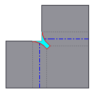
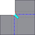
The following show auto-mitering on and off:
Auto-Mitering turned on. 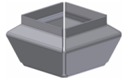
Auto-Mitering turned off. 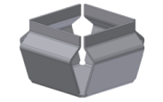
- On the Corner tab, click Apply Auto-Mitering.
- In the Miter Gap drop-down list, enter a value to change the size of an automatically applied gap between flanges.
Specify 2-bend or 3-bend Corner
You can specify this option when the selected geometry can be a 2-bend or 3-bend corner. When inactive, these options indicate the type of corner selected.
- Click 2 Bend Corner or 3 Bend Corner to enable the option.