To Create Presentation for a Model
Create a presentation file (IPN) and insert a model in the first scene. Create more scenes to work with different source models or different sets of representations in one presentation file.
What's New: 2025
To create a presentation file:
- From the application menu: Click File
 New. In the Create New File, select the default IPN template or locate and select other IPN template, and click Create.
- In an assembly file: Right-click the name of the assembly in the browser and select Create Presentation from the context menu. The view is based on the last active Design View Representation.
- From the application menu: Click File
In the Insert dialog box, locate and select a model file to be inserted in the first Scene.
To specify model representations, in the Select Assembly dialog box, click Options. Then in the File Open Options dialog box:
Select a Model State representation.
Select a Design View representation.
Select Associative to keep a link to the design view representation in the model file. If the design view representation is edited, the model in the presentation view updates with the edits.
Note: You can override the model settings in IPN scenes linked to design view representations. The overridden properties are then preserved in the IPN and ignore updates in the source model.Deselect Associative to break the link between the selected design view representation and the IPN file.
Select a positional representation.
Click OK to close the File Open Options dialog box.
Click Open to insert the model in the presentation file.
To Add a Scene to a Presentation
 In the Model browser, right-click the root node, and click Create Scene. Then select a source model file and model representations, and click Open.
You can copy a Scene and paste it into the presentation. The source model and all tweaks and actions from the source scene are included in the copy. You can rename scenes using your naming conventions.
To Manually Insert a Model in a Scene
When creating a presentation, you do not have to select the model immediately. You can save the empty file and add a model at a later time.
- In the QAT, click Presentation.
- Cancel the Open dialog box and save the file with the desired name.
- Return later, open the file and, in the ribbon click Presentation Model
 Insert Model.
 - Specify the representation to use and the associativity state you prefer.
- Click OK.
To Work with Design View Representations in a Scene
When you create a scene, you select a design view representation to use, and set the Associative option.
To change the design view representation or Associative setting for an existing scene, right-click the scene in the browser, and click Representations. Then edit the settings in the Representations dialog box, and click OK.
To edit component visibility or opacity in a presentation scene associative with a design view representation, either break the associativity or override the property. In the message box, select:
- Break to cancel associativity between the scene and the source design view representation. The Break button clears the Associative option in the Representations dialog box for the current scene.
- Override to block the design view associativity for the edited property. The Associativity option remains selected for the scene. If the design view representation in the source assembly changes, all property overrides in the scene are kept, and only original property values are updated.
Replace Model References in Presentations
Replace the current assembly file with another assembly.
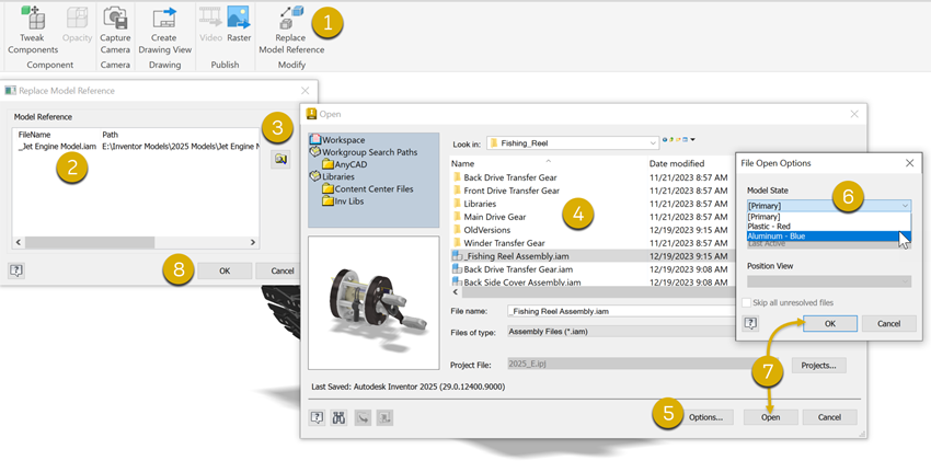
- On the ribbon, click Presentation tab Modify panel Replace Model Reference
 .
. - In the Replace Model Reference dialog, select the model being replaced.
- Click Select New Model
 to access the Open dialog.
 - Navigate to and select the replacement model file.
- (Optional) Click the Options button at the bottom of the dialog.
- (Optional) Select the model state to use in the presentation.
- Click OK, click Open, and click Yes.
- In the Replace Model Reference dialog, click OK.