Edit Dimension Reference
What's New: 2023
Access: |
- Right-click a drawing dimension and select Edit from the menu.
- Double-click a drawing dimension.
- The dialog box displays automatically when you create a general dimension and the option is selected.
|
Text
Edit box appends text to the calculated dimension value (represented by << >>), overwrites the calculated value, changes the justification of the entire body of text, and inserts special symbols. Tip: To stack text, type a correct stacking sequence, select it, right-click, and choose Stack. |
| | Left, Center, or Right Justification commands position the text relative to sides of the text box. |
| | Top, Middle, or Bottom Justification commands position the text relative to the top and bottom of the text box. |
Hide Dimension Value | Select the check box to replace the calculated value of the dimension with custom text. Clear the check box to restore the calculated value. |
| | Opens the Format Text dialog box to access advanced text formatting options. Note: The default dimension text format is controlled by the style settings in the active standard. |
Insert Symbol | Inserts a symbol into the text at the cursor position. Select a symbol from the list. |
Edit dimension when created | Displays the Edit Dimensions dialog box each time you insert a new general dimension so you can edit it immediately. Note: Alternatively, the option status can be set on the Drawing tab of the Application Options dialog box. |
Precision and tolerance
Specifies tolerance format for the selected dimensions in a drawing. Settings on the Precision and Tolerance tab override the settings of the associated dimension style in the current drawing.
Model Value | Shows the model value of the dimension. |
Override Displayed Value | Select the check box to turn off the calculated model value and allow entry of an override value. Clear the check box to restore the default calculated model value. |
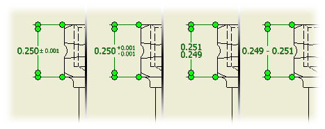
Tolerance Method | Specifies the tolerance method for the selected dimension. Scroll through the list and click to select a method. The tolerance method determines which other options in the dialog box are available. |
Upper Lower | Sets the value for the upper or lower tolerance. A value with a two-part sign of operation represents a range of tolerance. A value with a single sign of operation is either added to or subtracted from the nominal value. If a value has a single sign of operation, you can click to change the sign. |
Hole | Sets the tolerance value for the hole dimension when using Limits and Fits tolerance. Click the arrow, and then choose the tolerance from the list. |
Shaft | Sets the tolerance value for the shaft dimension when using Limits and Fits tolerance. Click the arrow, and then choose the tolerance from the list. |
Precision | Values are truncated and rounded to the specified precision. Click the arrow and select from the list. |
Primary Unit | Sets the number of decimal places for the primary units of the selected dimension. |
Primary Tolerance | Sets the number of decimal places for the primary tolerance of the selected dimension. |
Alternate Unit | Sets the number of decimal places for the alternate units of the selected dimension. |
Alternate Tolerance | Sets the number of decimal places for the alternate tolerance of the selected dimension. |
Inspection dimension
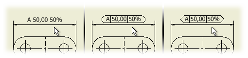
Inspection Dimension | Designates the selected dimension as an inspection dimension and activates inspection options. |
Shape | None Specifies no border shape surrounding the inspection dimension text.  Specifies rounded or angular ends as the desired shape of the inspection dimension. Specifies rounded or angular ends as the desired shape of the inspection dimension.
|
Label/Inspection Rate | Label contains text placed left of the dimension value. Click in the box and enter desired label text. Inspection Rate contains a percentage placed right of the dimension value. Click in the box and enter the inspection rate text. Symbol places the selected symbol in the active label or inspection rate box. |

