Roller Chain Calculation Basics
Chain Construction
The Roller Chains generator is intended to design chain drives with roller and bush chains. The chains can have single strand or multiple strands. The double-pitch chains are also supported. Typical construction of roller and bush chains is shown in the following picture. The main difference is that bush chain does not have a roller.
Bush chain components |
Roller chain components |
| |
If the chain length is an even number of pitches the connection link may be used to connect two ends of the chain together. The chain power capacity is not reduced usually.
If the chain length has an odd number of pitches, an offset link may be used at one end of the chain. Then the connecting link may be used to connect two ends of the chain together. The offset link usually reduces chain power capacity. The amount of power reduction is given by type and construction of the offset link. Consider the reduction of the chain power capacity you need to decrease chain construction factor.
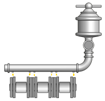
Repeated load tension
Chains in chain drives are loaded by cyclical tension so the chain is subject of fatigue. The typical load diagram is shown in the following picture. The load diagram may differ for different drive layouts.
|
|
Wear
Wear is important in designing roller chain drives. The roller chains are normally most affected by chain joint wear and sprocket wear.
Chain joint wear causes roller chains get longer. Sprockets for roller chains are designed to accept up to 3% (1.5% for double pitch chains) chain elongation from wear. When the chain elongates beyond that point it no longer fits the sprockets and the system will not operate properly. There might be different criteria for chain joint wear for large sprockets or drives with fixed center distance. If the worn chain is about to be replaced, we recommend that you replace the sprockets as well.
Chain joint wear |
Sprocket wear is considered as modification of the teeth shape. The teeth begin to take on a hooked shape. For idler sprockets usually wear at the bottom of the tooth space. When the tooth space is worn deeply enough, the chain rollers may bind against the tooth tops as they enter and leave the idler sprocket. The sprocket wear can be source of shock loads in the chain. Reversing the sprocket on the shaft can sometimes extend the life of worn sprocket.
Worn roller chain drive sprocket |
Worn roller chain idler sprocket |
Lubrication
Good lubrication must be provided for the chain drive to obtain longest life from a chain. The effective lubrication is a matter of applying the correct lubricant where it is most needed. The main problem is getting enough clean lubricant to the bearing surfaces of pins, bushings, and rollers.
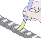
Lubricating oil should be free from contaminants, particularly abrasive particles.
Chain drive lubrication oil viscosity class is defined based on ambient temperature as:
Ambient temperature [°C] | -5 ≤ t ≤ +5 | +5 ≤ t ≤ +25 | +25 ≤ t ≤ +45 | +45 ≤ t ≤ +70 |
Oil viscosity class | VG 68 (SAE 20) | VG 100 (SAE 30) | VG 150 (SAE 40) | VG 220 (SAE 50) |
Adequate recommended lubrication is specified according to the chain size and speed and shown on following chart:
The progress of chain joint wear during chain service life with respect to quality of lubrication is shown in the following picture:
![]()
where:
a | No lubricated chain in soiled abrasive environment | |
b | Insufficient chain lubrication | |
c | Adequately lubricated chain |
Normally at the beginning of the chain service the wear progress rapidly and this stage it is known as initial wear. Initial wear can be minimized by pre-loading the chain what some manufacturers do. The pre-load can increase chain service life.
The chain joint wear then continue and the progress is slow what is known as normal wear. If the chain is adequately lubricated the chain joint wear continue to exhibit normal wear and eventually the chain run out its useful life. At the end of the useful life of a chain, the chain joint wear starts to rapidly progress again.
Ultimate tensile strength of the chain F U
The ultimate tensile strength of the chain is the highest load that the chain can withstand in a single application before breaking. It is not allowable working load either measuring load. The main value of a specification for minimum ultimate strength is to ensure that the chain was assembled properly. Roller Chain generator uses minimum ultimate tensile strength for determination of safety factors from chain breaking. Also, using additional factors it participates in calculation of expected chain links service life or link plates fatigue.
The default value of ultimate tensile strength comes from standard recommendations for given chain size but you may wish to consult this parameter with specifications provided by your chain manufacturer. The tensile strength may differ for the same size of the chain among different chain producers as well as different materials of the chain.
Specific chain mass m
Specific mass of the chain depends on the chain size, construction, and material. The default value is taken from standard recommendations or it is closest value of steel chains produced by chain manufacturers. The specific mass is used for computing centrifugal force as well as for vibration analysis.
Chain construction factor Φ
The chain construction factor describes the actual quality of the chain. It has direct impact to chain power rating as well as chain permissible bearing area pressure. The factor is usually equal to one. It is bigger than one if the chain is made from material with better strength or the quality of the chain is better than mentioned in national standards.
Chain power rating P R
Chain power rating represents chain capacity rating for specific operating conditions. Normally, the chain capacity is limited by link plate fatigue, roller and bushing impact fatigue and galling between the pin and bushing. See the typical power rating chart on the following image.
![]()
where:
A | chain drive power capacity limited by link plate fatigue | |
B | chain drive power capacity limited by roller and bush impact fatigue | |
C | chain drive power capacity limited by pin-bush galling |
Power correction factors
Chain power rating equations provide valid power capacity for chain drives what work under specific normal operation conditions. If your chain drive works under working condition what does not equal to the normal operation conditions, there is a need to introduce power correction factors as described below.
Normal operation conditions:
a chain drive with two sprockets on parallel horizontal shafts;
a small sprocket with 19 teeth;
a simplex chain without cranked link;
a chain length:
120 pitches for ISO chains,
100 pitches for ANSI, CSN chains;
a speed ratio of 1:3 or 3:1
an expected service life:
15000 hours ISO, ANSI, DIN chains,
10000 hours CSN chains;
an operating temperature between -5ºC and +70ºC;
sprockets correctly aligned and chain maintained in correct adjustment;
uniform operation without overload, shocks, or frequent starts;
clean and adequate lubrication throughout the life of the chain;
Shock factor Y
Service factor takes into account dynamic overloads dependent on the chain drive operating conditions, driver, and driven characteristics. The shock factor is used to determine size of the service factor as well as dynamic factor of safety. The peak loads caused by unexpected shocks and peak overloads can dramatically increase with large moments of inertia of driver or driven machine. By default the Chain generator uses following table to determine shock factor.
Service factor f 1
Service factor takes into account dynamic overloads dependent on the chain drive operating conditions and resulting, in particular, from the nature of the driver and driven elements. The valued of factor can be selected directly or using following table.
Driven machine characteristics | Driver machine characteristics | ||
Smooth running | Slight shocks | Moderate shocks | |
Smooth running | 1.0 | 1.1 | 1.3 |
Moderate shocks | 1.4 | 1.5 | 1.7 |
Heavy shocks | 1.8 | 1.9 | 2.1 |
Definitions of characteristics of driver machines
Definitions of characteristics of driven machines
By default the service factor is determined in accordance with shock factor as shown on the following chart:
![]()
where:
Y | shock factor [-] |
Sprocket size factor f 2
Sprocket size factor takes in an account number of teeth on the small sprocket. The factor is equal to one if power rating equations consider number of teeth of the smallest sprocket in the drive. Size of the smallest sprocket may have specific impact on each portion of chain power rating.
If you customize the chain power rating you need also revise sprocket size factor. If the power rating is specified from power rating tables with respect to number of teeth of the smallest sprocket the factor should remain equal to one. If the power rating provided is obtained from power rating chart where number of teeth of the smallest sprocket is not considered then you may need to adjust size of the factor. The sprocket size factor affects the design power. By default the Chain generator determines size of the factor as
![]()
![]()
where:
z s | Number of teeth on the small sprocket [-] |
Multiple strand factor f 3
Power ratings for single strand chains are given by power rating equations by default. The power ratings for multiple strand chains equal single-strand ratings multiplied by the multiple strand factor. By default, the program uses in-build table as shown in the following table. The multiple strand factor is also used in expected service life analysis.
Chain strands | 1 | 2 | 3 | 4 | 5 | 6 |
f 3 [-] | 1 | 1.7 | 2.5 | 3.3 | 3.9 | 4.6 |
Lubrication factor f 4
The lubrication factor tells the program how much inadequate lubrication impacts chain power capacity as well as service life. If the adequate lubrication is selected the size of the factor is equal to one what does not affect the analysis. If inadequate lubrication has to be used then the factor decreases chain power rating limited by pin-bush galling or the factor increases entire design power. By default the program uses following in-build table to indicate impact of selected lubrication.
Chain speed [m/s] | Lubrication factor [-] | |||
Lubrication | No lubrication | |||
Recommended | Insufficient | |||
Clean environment | Soiled environment | |||
up to 4 | 1 | 0.6 | 0.3 | 0.15 |
up to 7 | 0.3 | 0.15 | Inadmissible | |
up to 12 | Inadmissible | |||
more than 12 | ||||
Center distance factor f 5
The minimum center distance is one half the sum of outside sprocket diameters to avoid tooth interference. To ensure adequate wrap on the small sprocket (approximately 120 Degrees) it is suggested to have minimum center distance of the sum of the outside diameter of the large sprocket plus one half the outside diameter of the small sprocket.
It is good practice to set the center distance at 30 to 50 times the chain pitch. The longest practical center distance is about 80 times the chain pitch because chain sag and catenary tension become very large.
The center distance factor corrects the design power and takes into account difference of the actual center distance from the normal. The reason of the center distance factor comes from modification of load tension distribution and its affect to chain fatigue. By default the center distance factor is determined as follows.
![]()
where:
f 5 | center distance factor [-] | |
X B | number of chain links for normal operating conditions [-] | |
X | actual number of chain links in the drive [-] |
Ratio factor f 6
The ratio factor corrects the design power and takes into account difference of the transmission ratio from the normal. The reason of the ratio factor comes from modification of load tension distribution and its affect to chain fatigue. By default the ratio factor is determined from the following chart with respect to actual transmission ratio.
![]()
Transmission ratio is given from number of teeth of the driver and driven sprocket.
for z 1 < z 2 the i = z 2 / z 1
for z 1 > z 2 the i = z 1 / z 2
where:
f 6 | ratio factor [-] | |
i | transmission ratio [-] | |
z 1 | number of teeth of the driver sprocket [-] | |
z 2 | number of teeth of the driven sprocket [-] |
Service life factor f 7
The service life factor corrects the design power and takes into account difference of the required service life from the normal. By default the ratio factor is determined as
![]()
where:
f 7 | Service life factor [-] | |
L h | Required service life [hours] | |
L hB | Normal expected service life [hours] |
Pressure in chain bearing area analysis
During the chain drive service the fluctuating tensile load acts on contact surfaces between pins and bushings what causes specific size of chain bearing area pressure. If this pressure exceeds permissible pressure in chain bearing area the chain service life might significantly decrease. The amount of the actual pressure in chain bearing area is computed from maximum tension in chain span as follows
![]()
where:
p B | Actual pressure in chain bearing area [Pa] | |
F Tmax | Maximum tension in taught chain span [N] | |
A | Chain bearing area [m 2 ] |
Chain bearing area A
Chain bearing area is defined by width of internal chain link and pin diameter. The actual values are defined for each chain within XML data files.
|
| A = b 2 d 2 |
where: | |
A Chain bearing area [m 2 ] | |
b 2 Width of internal chain link [m] | |
d 2 chain pin diameter [m] |
Permissible pressure in chain bearing area p 0
The values of permissible pressure in chain bearing area shown on the chart below apply to normal operating conditions only. For specific operating conditions the value is corrected by specific friction factor λ what results in total permissible pressure. The total permissible pressure is then compared with the actual pressure in chain bearing area.
Permissible pressure specified here can be used for common steel chains. For chains made from different materials, you may need to adjust the permissible pressure accordingly.
![]()
The permissible pressure obtained from the previous chart is also corrected by chain construction factor so the amount of permissible pressure is defined as follows
p 0 = p B0 ϕ
where:
Specific friction factor λ
Specific friction factor corrects the permissible pressure in chain bearing area. The size of the factor depends on how much actual operating conditions differ from normal and it is defined as
![]()
where:
| λ | Specific friction factor [-] | |
f 1 | Service factor [-] | |
f 4 | Lubrication factor [-] | |
f 5 | Center distance factor [-] | |
f 6 | Ratio factor [-] | |
f 7 | Service life factor [-] |