To Copy, Move, or Rotate 2D Sketch Geometry
When you copy or move geometry in an Inventor sketch, you select one or more elements and then define a base point for the new location of the geometry. To rotate geometry, you select elements and then define a center point.
 Options panel).
Copy Geometry
In a 2D sketch, click Sketch tab
Modify panel Copy  .
.The Copy dialog box opens and Select mode is active by default.
(Optional) In the Copy dialog box, specify any of the following:
Optimize for Single Selection
Automatically switches to Base Point mode after you make a single selection in the graphics window. Choose this option if you’re only modifying one selection.
Precise Input
Invokes the Precise Input toolbar so that you can specify locations for modified geometry by entering specific X and Y coordinates.
Clipboard [Ctrl+C]
Saves a temporary copy of the selected geometry that you can paste into a different sketch.
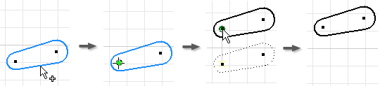
In the graphics window, select the geometry you want to copy:
- Click to select one element.
- Drag to create a selection set.
- Right-click and choose Select All.
If necessary, click Base Point in the Copy dialog box to switch to that mode.
Click in the graphics window to set the base point, or enter coordinates in the Precise Input toolbar.
Click in the graphics window or use the Precise Input toolbar to set the endpoint. Press Backspace to undo.
As you move the cursor, a dynamic preview shows dashed lines representing the original geometry and solid lines representing the copied geometry.
To finish, click Done in the Copy dialog box, right-click and choose Done, or press Esc.
Move Geometry
- In a 2D sketch, click Sketch tab Modify panel Move
 . The Move dialog box opens and Select mode is active by default.
 - (Optional) In the Move dialog box specify any of the following:
Optimize for Single Selection
Automatically switches to Base Point mode after you make a single selection in the graphics window. Choose this option if you’re only moving one selection.
Precise Input
Invokes the Precise Input toolbar so that you can specify locations for modified geometry by entering specific X and Y coordinates.
Copy
Moves a copy of the selection.
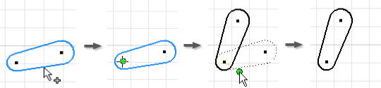
In the graphics window, select the geometry you want to move:
- Click to select one element.
- Drag to create a selection set.
- Right-click and choose Select All.
If necessary, click Base Point in the Move dialog box to switch to that mode.
Click in the graphics window to set the base point, or enter coordinates in the Precise Input toolbar.
Click in the graphics window or use the Precise Input toolbar to set the endpoint. Press Backspace to undo.
As you move the cursor, a dynamic preview shows dashed lines representing the original geometry and solid lines representing the moved geometry.
To finish, click Done in the Move dialog box, right-click and choose Done, or press Esc.
Rotate Geometry
- In a 2D sketch, click Sketch tab Modify panel Rotate
 . The Rotate dialog box opens and Select mode is active by default.
 - (Optional) In the Rotate dialog box specify any of the following:
Optimize for Single Selection
Automatically switches to Center Point mode after you make a single selection in the graphics window. Choose this option if you’re only rotating one selection.
Precise Input
Invokes the Precise Input toolbar so that you can specify locations for modified geometry by entering specific X and Y coordinates.
Copy
Rotates a copy of the selection.
In the graphics window, select the geometry you want to rotate:
- Click to select one element.
- Drag to create a selection set.
- Right-click and choose Select All.
If necessary, click Center Point in the Rotate dialog box to switch to that mode.
Click in the graphics window to set the center point, or enter coordinates in the Precise Input toolbar.
Click in the graphics window or use the Precise Input toolbar to set the endpoint. Press Backspace to undo.
As you move the cursor, a dynamic preview shows dashed lines representing the original geometry and solid lines representing the rotated geometry. In the Rotate dialog box, the Angle value updates dynamically.
In the Rotate dialog box, the Angle value updates dynamically.
Note: You can also specify the rotation Angle manually. If you enter a value, it remains fixed until you change it or click in the graphics window.To finish, click Done in the Rotate dialog box, right-click and choose Done, or press Esc.
Change Constraint Behavior when Moving or Rotating Geometry
If constraints prevent you from moving or rotating geometry, Inventor will open a dialog box to alert you. You can change this default behavior in the expanded area of the Move or Rotate command’s dialog box.
- To relax dimensional constraints when modifying geometry, click More
 in the Move or Rotate dialog box and choose an option to override the default behavior (Prompt):
Never
Dimensions do not relax. The operation obeys all dimensions associated with the selected geometry. If the operation fails, a dialog box appears.
If No Equation
Dimensions that are a function of any other dimension do not relax.
Always
After the operation completes, all linear and angular dimensions associated with the selected geometry recompute. Relaxes all dimensions outside the selection; ignores dimensions inside the selection.
Prompt
(Default) If the operation fails, a dialog box explains the problem and offers solutions.
- To break geometric constraints when modifying geometry, click More in the Move or Rotate dialog box and choose an option to override the default behavior (Prompt):
Never
Geometric constraints are unmodified. The operation obeys all existing geometric constraints. If the operation fails, a dialog box appears.
Always
Deletes only fixed constraints that are associated with the selected geometry. Deletes constraints between the selected and unselected geometry, except as follows:
- Move Except Parallel, Perpendicular, and Equal constraints
- Rotate Except Equal constraints
Prompt
(Default) If the operation fails, a message explains the problem.