To Work with Corner Seams in Sheet Metal Parts
You can create a corner seam or rip an existing corner seam between sheet metal faces. To create a three-bend corner, you can use Corner Seam or Auto-Miter.
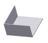
Create Corner Seam between Sheet Metal Faces
Create seams between faces that intersect or are coplanar.

- On the ribbon, click Sheet Metal tab
 Modify panel Corner Seam
  .
. - Select a model edge on each of two adjacent sheet metal faces.
- Accept the default seam type or select another of the three seam types.
- In the Corner Seam dialog box, you can:
- Use the Face/Edge distance measurement method instead of the defaulted Maximum Gap Distance method.
- Specify a percentage overlap value if you have elected to use a corner seam type of Overlap, or Reverse Overlap.
- Specify a gap value that differs from the Thickness parameter.
- Change the bend transition behavior and the corner relief (shape or size) from what is specified in the active style.
Create a Three-Bend Corner Seam
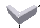
In most cases, you can use the Corner tab options in the Flange or Contour Flange dialog box to create a three-bend corner.
You can also create the corner seam manually from two nonintersecting flanges.
When you create the flat pattern, the corner relief type and radius size specified in the Corner tab of the feature applies. It does not display in the folded model.
The following steps detail the manual procedure:
- Create two nonintersecting flanges. One flange is typically an offset flange.
- On the ribbon, click Sheet Metal tab Modify panel Corner Seam .
- Select the edge on each flange closest to the appropriate mitered corner.
- For Gap, accept the default Thickness as specified in the current sheet metal style, or enter a value.
- (Optional) Select Measure, Show Dimensions, or List Parameters to enter a value.
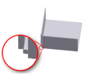
Rip Corner Seam on Converted Part Edge
Use Corner Seam Rip on part models that you convert to sheet metal models.
The thickness for converted part models must be uniform, and equal the material thickness defined in the active sheet metal style.
You can rip a corner seam to open an edge between faces. After you rip and clean up all corners, and manually apply bends, you can flatten your model. The resulting open corner typically leaves material that must be removed.
Create a sketch, and manually remove the material using a Cut.
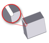
After the cut operation, apply Bend on the inside edges of what you would model as flanges.
Click Rip.
After you rip, clean up all corners, and manually apply bends, you can flatten your model.