To Create Basic Structural Frames
Start with an assembly file open.
 On the ribbon, click Design tab
  Frame panel Insert Frame.
Optionally:
 Select Copy properties and then select a member to match properties and orientation.
 Select a saved Preset to configure the frame member.
 Expand the Advanced Settings Menu in the upper right corner of the panel.
Note the checked defaults and make any required changes to the settings.
Set the geometry input type:
 To select 2D/3D sketch lines or model edges, set Specify frame location by two points OFF.Tip: Using this option you can highlight the sketch geometry and change the location of the origin and profile orientation by moving the cursor before you click.
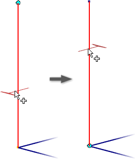
 To select points, set Specify frame location by two points ON.
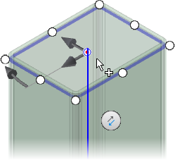
Select the Input Geometry in the graphics display.
Note: The radio buttons and manipulator arrows display where you click.After you select Input Geometry, use the display controls to set the zoom and view orientation.
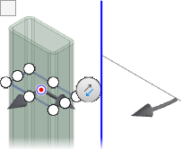
 Zooms and sets the view perpendicular to the frame manipulator.
 Zooms to the frame manipulator.
 Returns the display to the initial view.
 If required, click Flip Direction to reverse the orientation.
Specify the Frame Member:
Category
Note: Click Refresh Categories in the drop-down to rebuild the list and include custom read/write library entries.Standard
Family
Size
Material
Appearance
Optionally, check Merge Frame Members to select multiple edges and merge them into one frame member.
For example, you can select two edges and a bend between them. The result is one frame member that sweeps along the three entities.
Note: Merge Frame Members is not available for members placed with point selection.Specify the orientation.
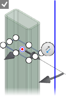
Select a radio button in the display to position the frame member.
Optionally:
Offset the frame by dragging a linear manipulator in the display or by entering a number in a value box.
Rotate the frame by dragging the angle manipulator in the display or by entering a rotation angle in the value box.
Tip: Double-click the angle manipulator to rotate in 45-degree increments. You can also hold the SHIFT key and drag the angle manipulator to rotate in 45-degree increments.
If you use an offset value you can:
Enable Rotate Around Selected point to use the radio button as the center of rotation.
Disable Rotate Around Selected Point to use the source geometry as the center of rotation.
- Optionally click Align selection and then click a linear edge, planar face, work axis, work plane, or sketch line to orient the member.
- Click Apply.
- When you insert the first frame member for a new frame in the active assembly, a new Frame subassembly is added in the browser under the active assembly.
- If there is no Frame subassembly in the active assembly document, the Create New Frame dialog box displays before the Frame Member Naming dialog box appears.
- Click OK in each dialog box to accept.
- Continue to add more frame members, as needed.
- When all frame members are added, click OK.
Visit the guided tutorial gallery for frame generator tutorials.