Constraining the model for a Warp analysis
For a Warp analysis, constraints are applied to the model nodes to:
- prevent rigid body motion (global translations and rotations) of the model, in response to the natural warpage of the part, or
- limit motion of the mounting nodes in order to consider assembly-induced deformations and stresses. For models scaled up by the mold shrinkage allowance, the adjustment of constraint positions according to mold shrinkage allowance must also be considered.
Note: General rigid-body motion in space involves six components (three orthogonal translations and three orthogonal rotations). This means that the minimum number of constrained degrees of freedom that must be set in the model is also six. In practice, you must decide whether the global coordinate system or a local coordinate system best simulates your perception of the physical situation being modeled.
Preventing rigid body motion
Automatic vs Manual constraints
By default, and for most cases, automatic constraints can be used to predict the typical deformation of a part.
If no manual constraints were set, then constraints are set automatically, and the deflection of the part is measured using the best-fit technique.
Although an automatic warpage calculation is often sufficient, it can also be useful to set manual constraints on a part in order to predict how it will warp if it is used in particular conditions, or if it is fixed to another object in an assembly for example.
You may want to set non-zero displacement constraints on specific nodes in order to consider assembly-induced deformations and stresses. In order to do this, you need to set rigid body motion constraints on the model first.
Figures 1 and 2 below show how warpage simulations can vary depending on the type of constraints that were set on the part.
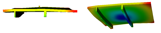
Typical deformation of a part with automatic constraints (scale factor=10.00)
However, setting specific constraints on a part enables early prediction of any unwanted behavior of a part in real conditions of use.
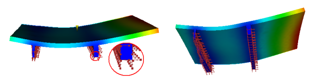
Simulation of the constraints that will be applied on the part when in use, and deflection resulting from these constraints. (scale factor=10.00)
Limiting the motion of the mounting nodes
You may want to set fixed constraints on specific mounting nodes in order to consider assembly-induced deformations and stresses if the injection molded part is going to be mounted into a rigid assembly. In order to do this, you need to set fixed warp constraints on the mounting nodes first. Then you need to turn on the adjustment of constraint positions according to mold shrinkage allowance option and specify the mold shrinkage allowance.