System-zones are graphic elements that are used to designate areas of the building that will be served by specific analytical air systems, water loops, and zone equipment.
When you create the energy analytical model, analytical spaces are added to all enclosed volumes in the 3D geometry. Every analytical space is assigned to any system-zone that it is inside or touching the zone. The relationship is displayed in the System Browser.
 By Space - Select spaces in your model to generate the boundary of the system-zone. Subsequent changes to the space geometry will update the boundary of the zone. System-zones created by space can be converted to a sketch-based system-zone.
 By Sketch - Use sketch tools to create a closed sketch to define a system-zone, or use sketch segments to cross spaces. Any analytical space either enclosed by the sketch boundary or crossed by a segment of the sketch is assigned to the system zone.
System-Zone By Space
To add a system-zone by space
- Open a plan view where spaces are visible.
- Click Analyze tab
 Zoning panel By Space
.
Zoning panel By Space
.
- To add a single space to the zone, place the cursor over a space, and after the space highlights, click to add the space to the zone.
To add multiple spaces to a zone, draw a selection box around the spaces being added, or press CTRL while selecting spaces one at a time.
- Click
 (Finish Editing Zone).
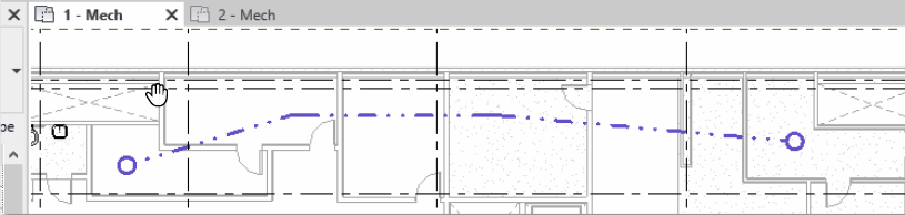
System-Zone By Sketch
To add a system-zone by sketching
- Open a plan view.
- Click Analyze tab Zoning panel By Sketch
.
Sketch mode is enabled.
- Draw lines and shapes as needed through every room that should be included in an area served by a specific analytical system. Any room or space that is touched by the line is included.
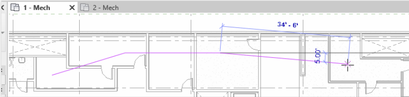 Alternatively, you can add a system-zone as a 2D shape using standard sketch tools. Anything inside the shape or touching the shape will be part of the system-zone.
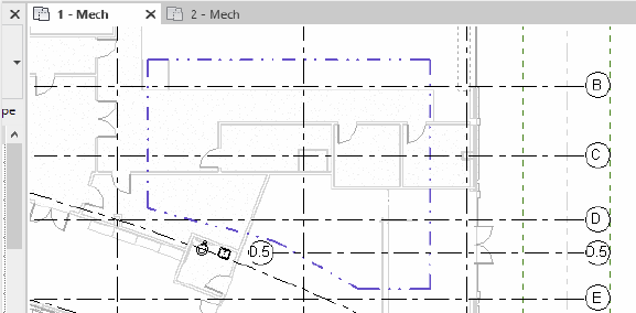
- Click
(Finish) to end the edit mode.
The system-zone is placed. To override the display settings, on the Analytical Model Categories tab, use the Visibility/Graphic Overrides dialog.
- Select the System-Zone to view its properties and assign zone equipment.