Customize the physical to analytical model automation to enhance the result based on your project particularities.
To customize the physical to analytical parameters:
- On the Analyze tab
 Structural Analytical Model panel, click
 (Analytical Automation).
- From the drop-down list, click
 (Run Physical to Analytical for Buildings).
Level Alignment
- Vertical elements - Columns and walls.
- Beams.
- Floors and slabs.
In addition to this factor, the Levels with the Structural parameters enabled have a higher priority compared to those without.
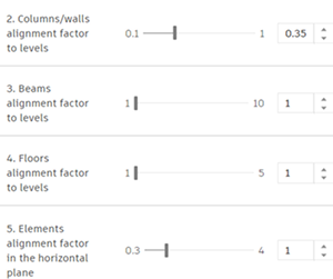
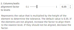
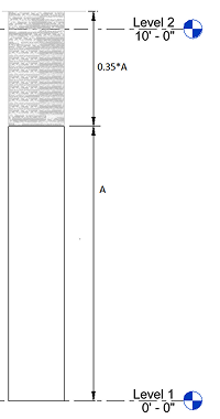
Columns/Walls alignment factor to levels
Adjust this factor to specify how far the automation tool should look for a level on which the closest end of the column/wall will be projected.
The default value is set to 0.35 of the column/wall height but could be adjusted up to 1.
|
|
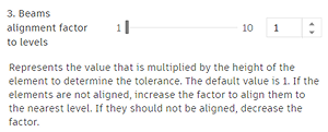
Beams alignment factor to levels
Adjust this factor to specify how far the automation tool should look for a level on which the analytical beam will be projected to.
The default value is set to 1 of the beam cross-section height but could be adjusted up to 10.
|
|
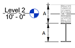
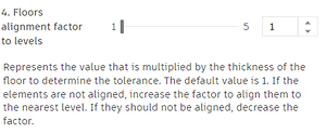
Floors alignment factor to levels
Adjust this factor to specify how far the automation tool should look for a level on which the analytical floor will be projected to.
The default value is set to 1 thickness height but could be adjusted up to 5.
|
|
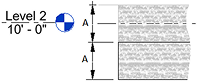
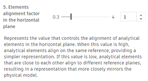
In-Plan Alignment
Allows you to customize how simplified the analytical model should be in terms of in-plan alignment.
The in-plan alignment is grouping the elements within a calculated tolerance to be aligned to the same reference. The calculated tolerance is an average of the thickness and cross-section width of all the selected walls and beams.
It can be multiplied by a factor. The default value of this factor is 1 and it can be multiplied up to 4 times.
To customize the wall thickness setting:
When Use Structural Thickness is enabled, the analytical model automation will use the wall/floor/slab's structural layer thickness when creating or updating the analytical panel.
- In the Analyze tab Structural Analytical Model panel, click
(Analytical Automation).
- From the drop-down list, select
(Run Physical to Analytical for Buildings).
- In Modify | Settings, for Analytical Panel, click the check box for Use Structural Thickness.