Learn how to place schematic bending details on your reinforcement drawings.
You can add multiple rebar to the same schematic bending detail, using the Add / Remove Host option, during placement or add more hosts (leaders) to existing schematic bending details.
To place schematic bending details with a single leader
- In the Annotate tab
 Symbol panel, click
 (Bending Detail).
- Select
 (Schematic) from the Modify | Place Bending Detail tab Type panel.
- Select one bar in a rebar set.
- Click to place the schematic bending detail.
- If
 (Add / Remove Host) in Modify | Place Bending Detail Host panel is toggled ON, click in empty space to finish placing the current schematic bending detail
- Optionally, you can choose the position of the bending detail relative to the embedded tag, from the properties palette or by pressing Space bar.
Alternatively, select one rebar set and in the Modify | Structural Rebar contextual ribbon Symbol panel, click
(Bending Detail). If the last used type was not schematic, you can click
(Schematic) in Modify | Place Bending Detail Type panel and click to place the bending detail.
Bending Detail Position:
 - Left
 - Right
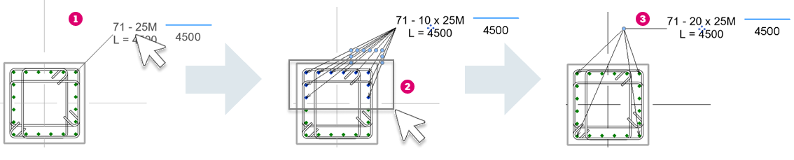
To place schematic bending details with multiple leaders
- In the Annotate tab Symbol panel, click
(Bending Detail).
- Select
(Schematic) from the Modify | Place Bending Detail tab Type panel.
- Click to activate
(Add / Remove Host) in the Host panel.
- Select one bar and click to place the schematic bending detail. You can also edit the leader visibility during placement.
- Select additional bars to add leaders to.
- Click in empty space to finish placing the schematic bending detail. You can now repeat steps 4 - 6 to create more schematic bending details.
- Click in empty space again, click Modify or press Esc to finish the placement.
For an existing schematic bending details, you can add or remove rebar by selecting the schematic bending detail and clicking
(Add / Remove Host) in the Modify | Place Bending Detail tab Host panel.
 by selecting a schematic bending detail and choosing one of the options in Modify | Bending Detail tab Leader panel. These options include showing all leaders, just one leader, showing no leaders or choosing which leaders to show.
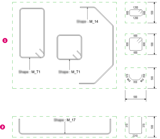
Schematic bending detail scaling
The bending detail geometry is scaled uniformly for stirrups and rebar shapes with at least one angle different than 90 degrees
and scaled non-uniformly (different x and y scale) for rebar shapes with 90-degree angles between the segments and style set to standard
.
The orientation of the bending detail is the same as the rebar shape family, with a plus or minus 90-degree rotation to fit better inside the box defined by the specified width and height.